Manuals
/
Sony Ericsson
/
Home Audio
/
CD Player
Sony Ericsson
XR-C7500RX
service manual
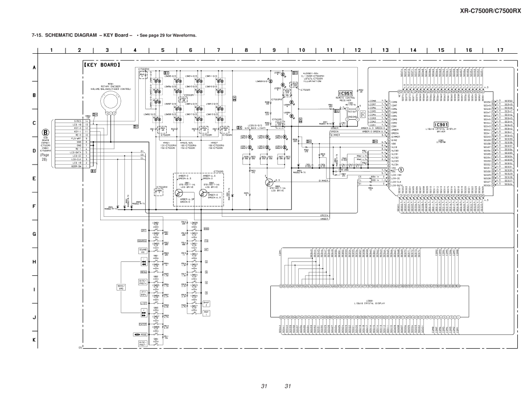
Schematic Diagram KEY Board See page 29 for Waveforms
Models:
XR-C7500RX
1
31
52
52
Download
52 pages
24.69 Kb
28
29
30
31
32
33
34
35
Specs
Power connection diagram
Signal Path MW/LW Tape Play
Printed Wiring Board KEY Board
Reset button
Section Disassembly
Section Mechanical Adjustments
Setting the clock
SWITCH, Tactile with LED
Housing
Page 31
Image 31
XR-C7500R/C7500RX
7-15.
SCHEMATIC DIAGRAM – KEY Board –
See
•
page 29 for Waveforms.
(Page
28)
31 31
Page 30
Page 32
Page 31
Image 31
Page 30
Page 32
Contents
XR-C7500R/C7500RX
Specifications
General
Table of Contents
Diagrams
Section Servicing Notes
Section General
Setting the clock
Installation Instalación Montering Instalação
Reset button
Connections Conexiones Anslutning Ligações
Connection example Ejemplo de conexiones
XR-C7500R/XR-C7500RX AEP, UK
XR-C7500RX E
Power connection diagram
SUB Panel ASS’Y
Section Disassembly
Mechanism Deck MG-25G-136
Heat Sink 2P
Main Board
Housing
Section Assembly of Mechanism Deck
ARM Suction
Gear LDG-FT
Lever LDG-A / LDG-B
Mounting Position of CAPSTAN/REEL Motor M901
Guide C
Tape Tension Measurement
Section Mechanical Adjustments
Section Electrical Adjustments
Torque Measurement
Tuner Section
Tape Speed Adjustment
Dolby Level Adjustment
Tape Deck Section
Section
Diagrams
Block Diagram TUNER/TAPE Section
Signal Path MW/LW Tape Play
Signal Path
Block Diagram Main Section
Remote
Block Diagram DISPLAY/KEY Control Section
BUS-ON
Block Diagram BUS CONTROL/POWER Supply Section
BUS Audio Tape Play
Semiconductor Location Component Side
Printed Wiring Board Main Board Component Side
Semiconductor Location Conductor Side
Printed Wiring Board Main Board Conductor Side
XR-C7500R/C7500RX
XR-C7500R/C7500RX
XR-C7500R/C7500RX
XR-C7500R/C7500RX
Printed Wiring Board SUB Board Schematic Diagram SUB Board
KEY Board
Waveforms Main Board
Printed Wiring Board KEY Board
Schematic Diagram KEY Board See page 29 for Waveforms
IC50 SAA6588T/V2-118
IC Block Diagrams Main Board IC10
IC100 CXD2726Q-4
IC250 CXA2510AQ-T4
IC201
IC500 BA8270F-E2
Pin No Pin Name Description
IC PIN Function Description
Xlat
Main Board IC600 MB90574BPMT-G-265-BND System Controller
Dsplat
Accin
Stop Loading Eject Brake
TUX1 Except E
54 3-041-003-01 Button LIST/ENTER DSPL. LIST. Enter
Front Panel Section
60 1-694-660-11 Conductive BOARD, Connection
164
Mechanism Deck Section MG-25G-136
159 158 155 154 157 156 153152 168 151 160 163
161 162
Section Electrical Parts List KEY
Rotary Encoder
Resistor
Metal Chip
RES-CHIP
Ceramic Chip 8PF
SWITCH, Tactile with LED
KEY Main
SEEK/AMS + M
Double Layer
Tantalum
Diode CRZ22 TE85L.SONY
Film
Diode DTZ5.6B
Diode MA152WA-TX
RN5VD33AA-TL
TDA7402TR
LB1930M-TLM
BA09ST-V5
R27 216-809-11
Type C
Main SUB
508 507
501 502
503 504 505
506 507
Top
Page
Image
Contents