dB | HF Section |
|
|
|
|
20.0 |
|
|
|
|
|
15.0 |
|
|
|
|
|
10.0 |
|
|
|
|
|
5.0 |
|
|
|
|
|
0.0 |
|
|
|
|
|
|
|
|
|
| |
|
|
|
|
| |
|
|
|
|
| |
|
|
|
|
| |
20 | 100 | 1k | 10k | 20k | |
|
|
| Frequency/Hz |
|
|
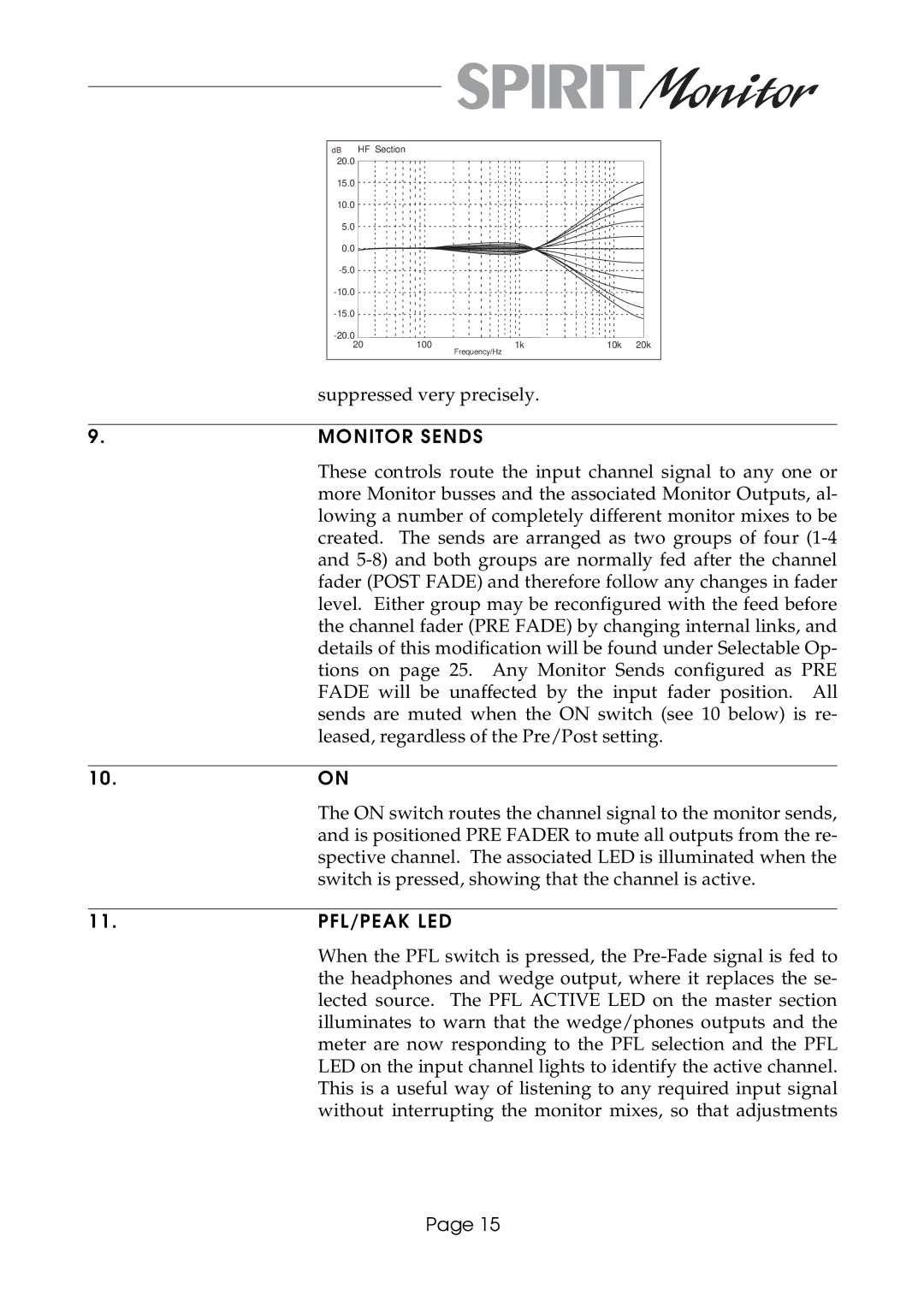
| suppressed very precisely. | |
|
| |
9. | MONITOR SENDS |
|
| These controls route the input channel signal to any one or | |
| more Monitor busses and the associated Monitor Outputs, al- | |
| lowing a number of completely different monitor mixes to be | |
| created. The sends are arranged as two groups of four | |
| and | |
| fader (POST FADE) and therefore follow any changes in fader | |
| level. Either group may be reconfigured with the feed before | |
| the channel fader (PRE FADE) by changing internal links, and | |
| details of this modification will be found under Selectable Op- | |
| tions on page 25. Any Monitor Sends configured as PRE | |
| FADE will be unaffected by the input fader position. All | |
| sends are muted when the ON switch (see 10 below) is re- | |
| leased, regardless of the Pre/Post setting. | |
|
| |
10. | ON |
|
| The ON switch routes the channel signal to the monitor sends, | |
| and is positioned PRE FADER to mute all outputs from the re- | |
| spective channel. The associated LED is illuminated when the | |
| switch is pressed, showing that the channel is active. | |
|
| |
11. | PFL/PEAK LED |
|
| When the PFL switch is pressed, the | |
| the headphones and wedge output, where it replaces the se- | |
| lected source. The PFL ACTIVE LED on the master section | |
| illuminates to warn that the wedge/phones outputs and the | |
| meter are now responding to the PFL selection and the PFL | |
LED on the input channel lights to identify the active channel. This is a useful way of listening to any required input signal without interrupting the monitor mixes, so that adjustments
Page 15