Hardware Installation |
|
|
|
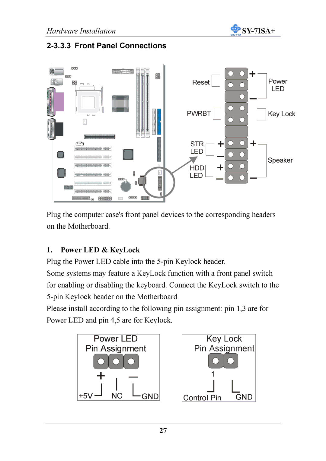
Reset |
| + | Power | |
|
| _ | LED | |
|
|
| ||
PWRBT |
|
| Key Lock | |
STR | + | + |
| |
LED | _ |
| Speaker | |
HDD | + | _ | ||
| ||||
LED | _ |
|
Plug the computer case's front panel devices to the corresponding headers on the Motherboard.
1.Power LED & KeyLock
Plug the Power LED cable into the
Some systems may feature a KeyLock function with a front panel switch for enabling or disabling the keyboard. Connect the KeyLock switch to the
Please install according to the following pin assignment: pin 1,3 are for Power LED and pin 4,5 are for Keylock.
Power LED
Pin Assignment
+ ![]() _
_
+5V ![]() NC
NC ![]() GND
GND
Key Lock
Pin Assignment
1
Control Pin GND
27