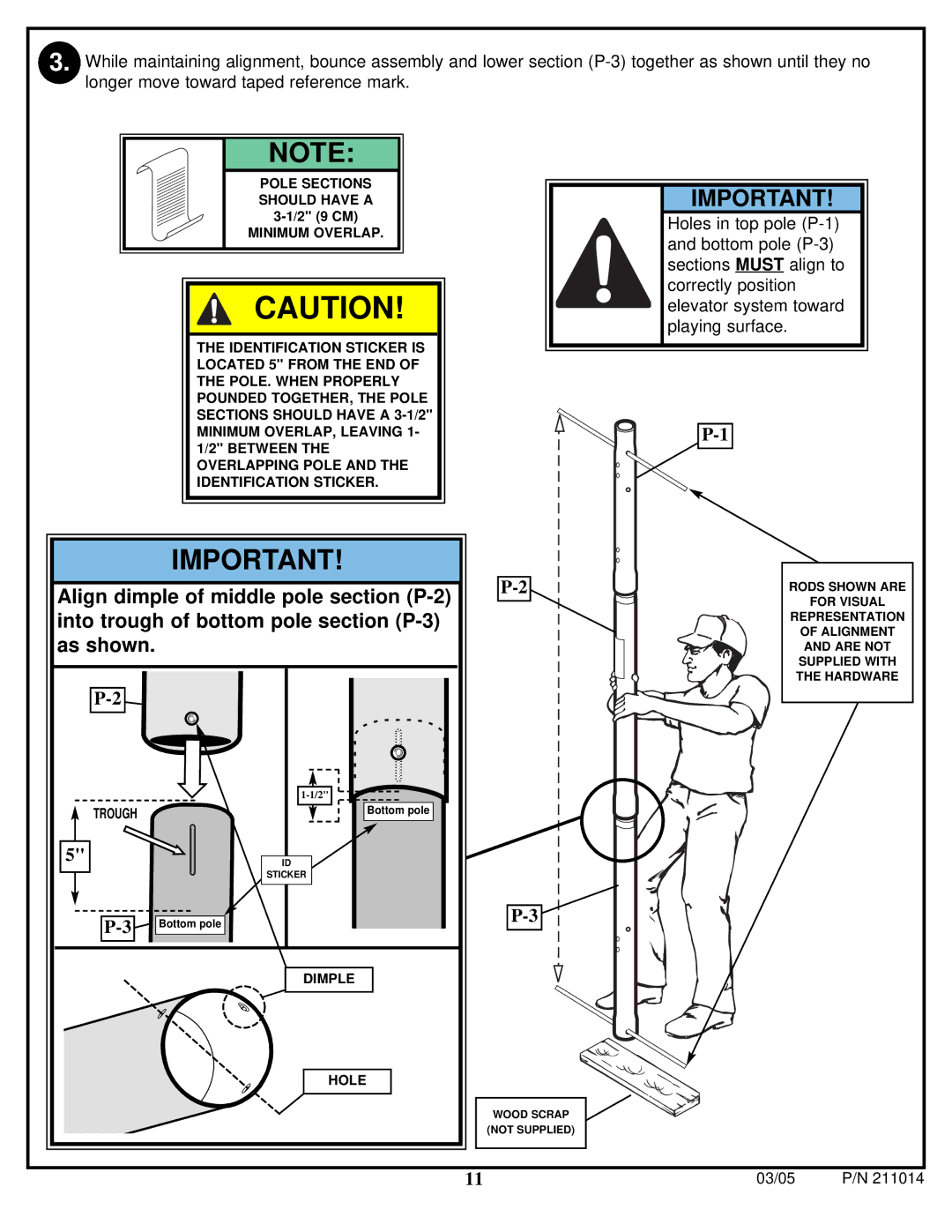
3. While maintaining alignment, bounce assembly and lower section
NOTE: |
POLE SECTIONS |
SHOULD HAVE A |
MINIMUM OVERLAP. |
CAUTION!
THE IDENTIFICATION STICKER IS LOCATED 5" FROM THE END OF THE POLE. WHEN PROPERLY POUNDED TOGETHER, THE POLE SECTIONS SHOULD HAVE A
MINIMUM OVERLAP, LEAVING 1- 1/2" BETWEEN THE OVERLAPPING POLE AND THE IDENTIFICATION STICKER.
IMPORTANT!
Align dimple of middle pole section
IMPORTANT!
Holes in top pole
RODS SHOWN ARE
FOR VISUAL
REPRESENTATION
OF ALIGNMENT
AND ARE NOT
SUPPLIED WITH
THE HARDWARE
TROUGH
5"
![]()
![]()
Bottom pole
ID
STICKER
| Bottom pole | |
|
| |
|
|
|
DIMPLE
HOLE
WOOD SCRAP
(NOT SUPPLIED)
11 | 03/05 | P/N 211014 |
|
|
|