
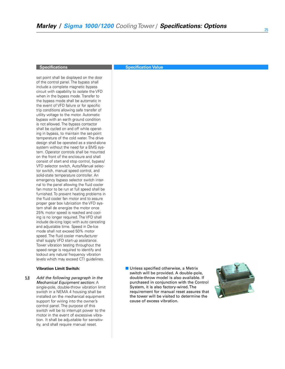
1000, 1200 specifications
SPX Cooling Technologies, a prominent player in the cooling solutions market, is known for its cutting-edge designs and innovations in the field of cooling systems. Among its notable offerings are the SPX Cooling Technologies 1200 and 1000 series, which are engineered to meet the demands of various industrial applications.The SPX Cooling Technologies 1200 series is renowned for its efficiency and robust construction. One of its main features is its modular design, allowing for easy installation and maintenance. This series is equipped with advanced cooling technology, enhancing energy efficiency while minimizing operating costs. The 1200 series utilizes a counterflow design, promoting improved heat exchange and a more direct airflow pattern. This results in higher thermal performance and reduced energy consumption, making it an ideal choice for operations that prioritize sustainability and cost-effectiveness.
On the other hand, the SPX Cooling Technologies 1000 series is tailored for versatility and reliability. This series boasts a design that accommodates a range of capacities and configurations, making it suitable for diverse applications, including HVAC, industrial processes, and power generation. One of the standout characteristics of the 1000 series is its handling of large thermal loads with minimal pressure drop, which ensures optimal performance in challenging conditions. Its corrosion-resistant materials enhance durability, making it resilient in harsh environments.
Both series incorporate advanced fan technology, which is designed to maximize airflow while minimizing noise levels. The fans are individually controllable, allowing for precise adjustments to meet specific cooling demands. Furthermore, these cooling towers are designed with user-friendly accessibility, simplifying maintenance and inspection processes, thereby reducing downtime.
SPX Cooling Technologies also places a significant emphasis on innovation. Both the 1200 and 1000 series are built with predictive maintenance capabilities, leveraging IoT technologies to monitor performance metrics in real time. This proactive approach enables facility managers to anticipate maintenance needs and address issues before they escalate into costly failures.
In summary, the SPX Cooling Technologies 1200 and 1000 series represent a substantial advancement in cooling technology, providing efficient, reliable, and modular solutions for various industrial applications. Their design, efficiency, and advanced features position them as leaders in the market, responding to the evolving needs of industries worldwide.