Operation
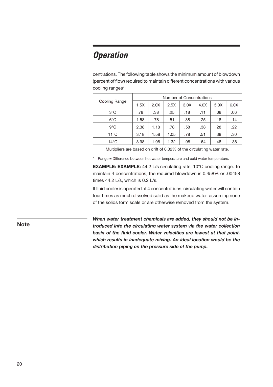
centrations. The following table shows the minimum amount of blowdown (percent of flow) required to maintain different concentrations with various cooling ranges*:
Cooling Range |
|
| Number of Concentrations |
|
| ||||
|
|
|
|
|
|
|
|
| |
1.5X | 2.0X |
| 2.5X | 3.0X | 4.0X |
| 5.0X | 6.0X | |
|
|
| |||||||
3°C | .78 | .38 |
| .25 | .18 | .11 |
| .08 | .06 |
|
|
|
|
|
|
|
|
|
|
6°C | 1.58 | .78 |
| .51 | .38 | .25 |
| .18 | .14 |
|
|
|
|
|
|
|
|
|
|
9°C | 2.38 | 1.18 |
| .78 | .58 | .38 |
| .28 | .22 |
11°C | 3.18 | 1.58 |
| 1.05 | .78 | .51 |
| .38 | .30 |
|
|
|
|
|
|
|
|
|
|
14°C | 3.98 | 1.98 |
| 1.32 | .98 | .64 |
| .48 | .38 |
|
|
|
|
|
|
|
|
|
|
Multipliers are based on drift of 0.02% of the circulating water rate.
*Range = Difference between hot water temperature and cold water temperature.
EXAMPLE: EXAMPLE: 44.2 L/s circulating rate, 10°C cooling range. To maintain 4 concentrations, the required blowdown is 0.458% or .00458 times 44.2 L/s, which is 0.2 L/s.
If fluid cooler is operated at 4 concentrations, circulating water will contain four times as much dissolved solid as the makeup water, assuming none of the solids form scale or are otherwise removed from the system.
When water treatment chemicals are added, they should not be in-
Notetroduced into the circulating water system via the water collection basin of the fluid cooler. Water velocities are lowest at that point, which results in inadequate mixing. An ideal location would be the distribution piping on the pressure side of the pump.
20