HYDRAULIC GROUP ILLUSTRATION
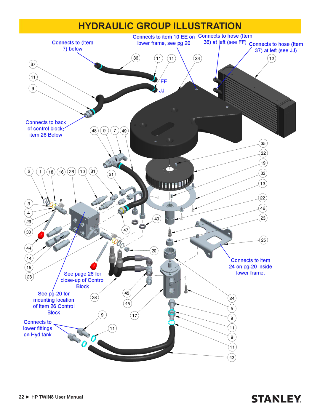
Connects to (Item
7) below
37
11
9
Connects to back
of control block,48 9 7 49 item 26 Below
Connects to item 10 EE on | Connects to hose (Item | |||
lower frame, see pg 20 |
| 36) at left (see FF) Connects to hose (Item | ||
|
|
|
| 37) at left (see JJ) |
36 | 11 | 11 | 34 | 12 |
FF
JJ
2 | 1 | 18 | 16 | 26 | 10 | 31 | 21 |
|
|
|
|
|
|
|
3 |
|
|
|
4 |
|
|
|
29 |
|
| 40 |
|
|
| |
30 |
|
| 47 |
|
|
| |
44 |
|
| 20 |
|
|
| |
14 |
|
|
|
15 |
|
|
|
28 | See page 26 for |
| |
| |||
|
| ||
|
| Block |
|
| See | 38 | 45 |
| mounting location |
| |
|
| 45 | |
| of Item 26 Control |
| |
|
|
| |
| Block | 9 | 17 |
|
| ||
Connects to |
|
| |
lower fittings |
| 11 | |
on Hyd tank |
|
| |
35
32
19
33
13
22
46
23
25
Connects to item 24 on
24
5
9
11
9
11
![]() 42
42
22 ► HP TWIN8 User Manual