NAMES AND FUNCTIONS
LCD
![]()
![]()
![]()
![]()
![]()
![]()
![]()
![]()
![]()
![]()
![]() ELAPSED
ELAPSED
REMAIN
SINGLE
CONTINU
|
|
|
|
|
|
|
|
|
|
|
| TRACK |
| M |
| S |
|
| F | ||
|
|
|
|
|
|
|
|
|
|
|
|
|
|
|
|
|
|
|
|
|
|
2425 26 27 28 29 30 31 32 33
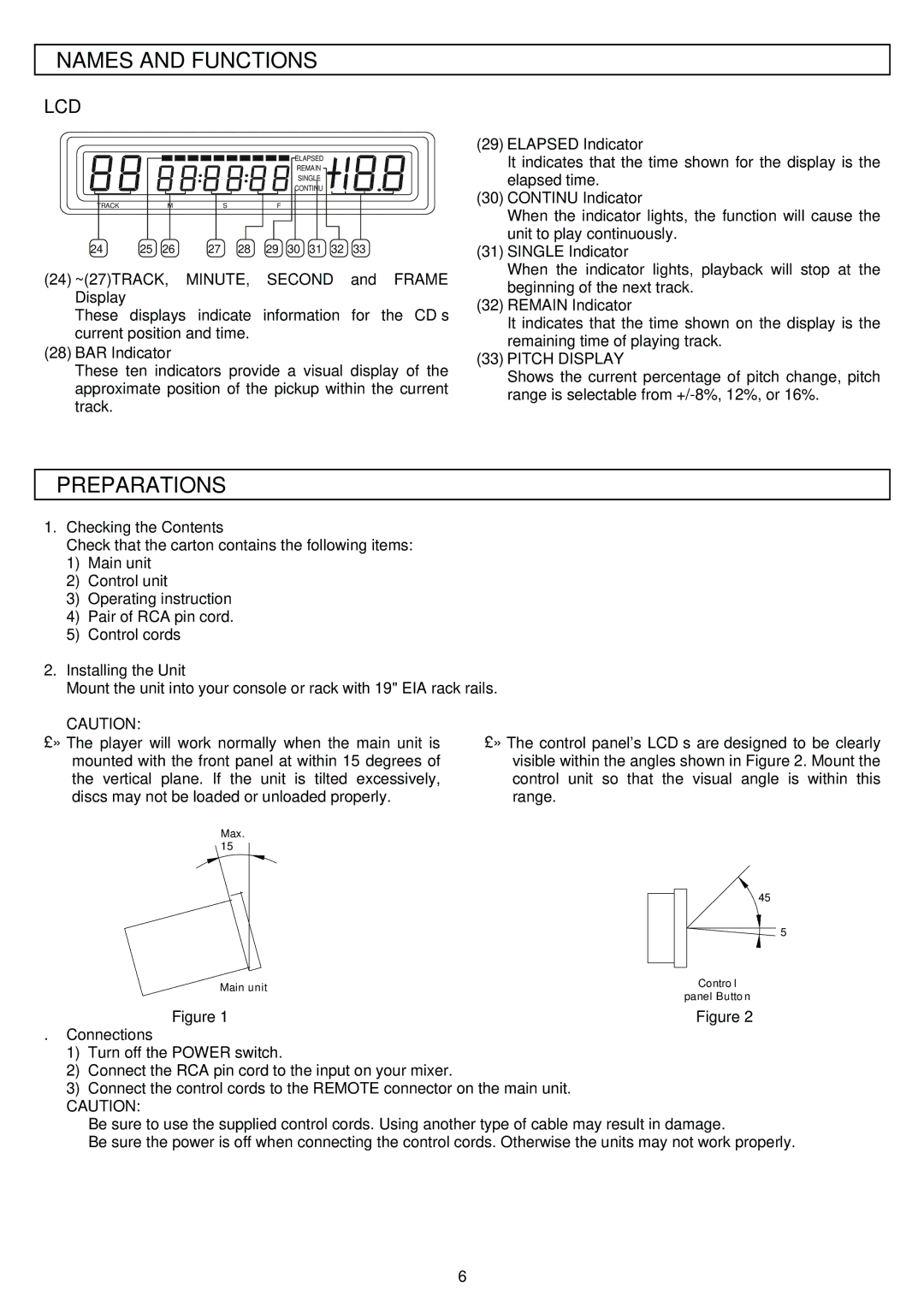
(24)~(27)TRACK, MINUTE, SECOND and FRAME Display
These displays indicate information for the CD’s current position and time.
(28)BAR Indicator
These ten indicators provide a visual display of the approximate position of the pickup within the current track.
(29)ELAPSED Indicator
It indicates that the time shown for the display is the elapsed time.
(30)CONTINU Indicator
When the indicator lights, the function will cause the unit to play continuously.
(31)SINGLE Indicator
When the indicator lights, playback will stop at the beginning of the next track.
(32)REMAIN Indicator
It indicates that the time shown on the display is the remaining time of playing track.
(33)PITCH DISPLAY
Shows the current percentage of pitch change, pitch range is selectable from
PREPARATIONS
1.Checking the Contents
Check that the carton contains the following items:
1)Main unit
2)Control unit
3)Operating instruction
4)Pair of RCA pin cord.
5)Control cords
2.Installing the Unit
Mount the unit into your console or rack with 19" EIA rack rails.
CAUTION: | The control panel's LCD’s are designed to be clearly | |||
The player will work normally when the main unit is | ||||
耟 | 耟 | |||
mounted with the front panel at within 15 degrees of | visible within the angles shown in Figure 2. Mount the | |||
the vertical plane. If the unit is tilted excessively, | control unit so that the visual angle is within this | |||
discs may not be loaded or unloaded properly. | range. | |||
Max. |
|
|
|
|
15° |
|
|
|
|
|
|
|
|
|
|
|
| 45° | |
|
| |||
|
| 5° | ||
Main unit |
|
|
| Control |
|
|
| ||
|
| panel Button | ||
|
|
| ||
Figure 1 |
|
|
| Figure 2 |
. Connections
1)Turn off the POWER switch.
2)Connect the RCA pin cord to the input on your mixer.
3)Connect the control cords to the REMOTE connector on the main unit.
CAUTION:
• Be sure to use the supplied control cords. Using another type of cable may result in damage.
• Be sure the power is off when connecting the control cords. Otherwise the units may not work properly.
6