DP8340RC specifications
The Star Micronics DP8340RC is a robust dot matrix printer designed primarily for receipt and ticket printing. Known for its reliability and efficiency, it is a popular choice for various businesses, including retail, hospitality, and transportation industries. With its compact design and high performance, the DP8340RC is capable of meeting the demands of high-volume printing tasks.One of the key features of the DP8340RC is its print speed, which reaches up to 550 characters per second. This rapid printing capability ensures that transactions can be completed swiftly, enhancing customer service in busy environments. Its 9-pin print head and high-resolution output allow for crisp and clear text, which is essential for legibility in printed receipts and tickets.
In terms of technology, the DP8340RC operates on an advanced impact printing mechanism, which is not only cost-effective but also performs reliably over extended periods. This technology allows the printer to produce high-quality output on various types of media, including multi-part forms, making it versatile for various applications. The printer supports a wide range of paper widths, which further enhances its usability in different business scenarios.
The design of the DP8340RC also focuses on ease of use. It features a user-friendly interface with simple controls, allowing even non-technical staff to operate it without challenges. The printer's paper loading mechanism is straightforward, minimizing downtime and improving overall efficiency during high-demand periods.
Durability is another strong suit of the DP8340RC. Built to withstand the rigors of retail and hospitality environments, it boasts a long lifespan, requiring minimal maintenance. This reliability results in lower overall operational costs, making it a wise investment for businesses looking to streamline their printing processes.
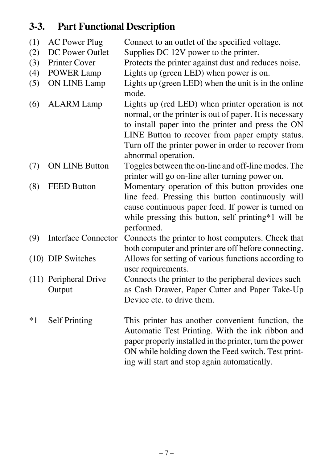
Connectivity options are a critical consideration for modern printers, and the DP8340RC excels in this area as well. It offers multiple interface options, including USB, parallel, and serial connections, ensuring compatibility with various systems and devices.
In conclusion, the Star Micronics DP8340RC is a reliable, efficient, and versatile dot matrix printer that caters to the critical needs of businesses across multiple industries. With its fast print speed, durable construction, and user-friendly design, it remains a top choice for organizations looking to optimize their point-of-sale and ticketing processes.
