Operator Control Panel and Display
The function of keys F1 to F4 is shown by a
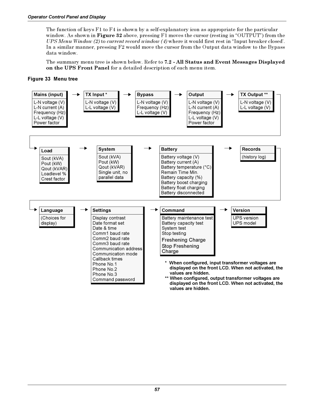
The summary menu tree is shown below. Refer to 7.2 - All Status and Event Messages Displayed on the UPS Front Panel for a detailed description of each menu item.
Figure 33 Menu tree
Mains (input)
TX Input *
Bypass
Output
TX Output **
Load | System | Battery | Records |
Sout (kVA) | Sout (kVA) | Battery voltage (V) | (history log) |
Pout (kW) | Battery current (A) |
| |
Pout (kW) |
| ||
Qout (kVAR) | Battery temperature (°C) |
| |
Qout (kVAR) |
| ||
Single unit, no | Remain Time Min. |
| |
Loadlevel % |
| ||
Crest factor | parallel data | Battery capacity (%) |
|
| Battery boost charging |
| |
|
|
| |
|
| Battery float charging |
|
|
| Battery disconnected |
|
Language | Settings | Command | Version |
(Choices for | Display contrast | Battery maintenance test |
| UPS version | |||
display) | Date format set | Battery capacity test |
| UPS model | |||
|
| Date & time | System test |
|
|
| |
|
|
|
|
| |||
|
| Comm1 baud rate | Stop testing |
|
|
| |
|
| Comm2 baud rate | Freshening Charge |
|
|
| |
|
| Comm3 baud rate | Stop Freshening |
|
|
| |
|
| Communication address |
|
|
| ||
|
| Charge |
|
|
| ||
|
| Communication mode |
|
|
| ||
|
|
|
|
|
| ||
|
| Callback times | * When configured, input transformer voltages are | ||||
|
| Phone No.1 | |||||
|
| Phone No.2 | displayed on the front LCD. When not activated, the | ||||
|
| Phone No.3 | values are hidden. |
|
|
| |
|
| Command password | ** When configured, output transformer voltages are | ||||
|
|
|
| displayed on the front LCD. When not activated, the | |||
|
|
|
| ||||
|
|
|
| values are hidden. |
|
|
|
57
