UPS
3.4.4Control Wires
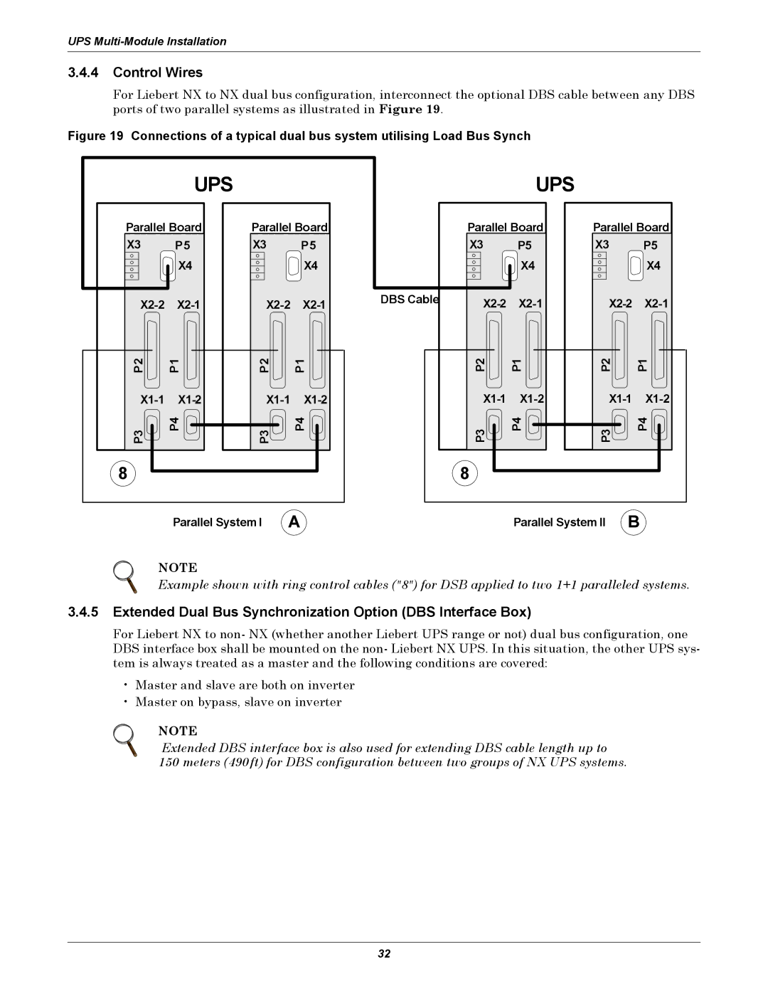
For Liebert NX to NX dual bus configuration, interconnect the optional DBS cable between any DBS ports of two parallel systems as illustrated in Figure 19.
Figure 19 Connections of a typical dual bus system utilising Load Bus Synch
| UPS |
|
|
Parallel Board | Parallel Board | ||
X3 | P5 | X3 | P5 |
| X4 |
| X4 |
| |||
P2 | P1 | P2 | P1 |
| |||
P3 | P4 | P3 | P4 |
8 |
|
|
|
| Parallel System I | A | |
|
| UPS |
|
|
| Parallel Board | Parallel Board | ||
| X3 | P5 | X3 | P5 |
|
| X4 |
| X4 |
DBS Cable |
| |||
| ||||
| P2 | P1 | P2 | P1 |
|
| |||
| P3 | P4 | P3 | P4 |
| 8 |
|
|
|
|
| Parallel System II | B | |
NOTE
Example shown with ring control cables ("8") for DSB applied to two 1+1 paralleled systems.
3.4.5Extended Dual Bus Synchronization Option (DBS Interface Box)
For Liebert NX to non- NX (whether another Liebert UPS range or not) dual bus configuration, one DBS interface box shall be mounted on the non- Liebert NX UPS. In this situation, the other UPS sys- tem is always treated as a master and the following conditions are covered:
•Master and slave are both on inverter
•Master on bypass, slave on inverter
NOTE
Extended DBS interface box is also used for extending DBS cable length up to 150 meters (490ft) for DBS configuration between two groups of NX UPS systems.
32