Operation
5.1.2Static Transfer Switch
The circuit blocks labeled Static Switch in Figure 27 contain electronically controlled switching cir- cuits that enable the critical load to be connected to either the inverter output or to a bypass power source via the static bypass line. During normal system operation the load is connected to the inverter; but in the event of a UPS overload or inverter failure, the load is automatically transferred to the static bypass line.
To provide a clean
A manually controlled, maintenance bypass supply is incorporated into the UPS design. It enables the critical load to be powered from the utility (bypass) supply while the UPS is shut down for routine maintenance.
NOTE
When the UPS is operating in bypass mode or on maintenance bypass, the connected equipment is not protected from power failures or surges and sags.
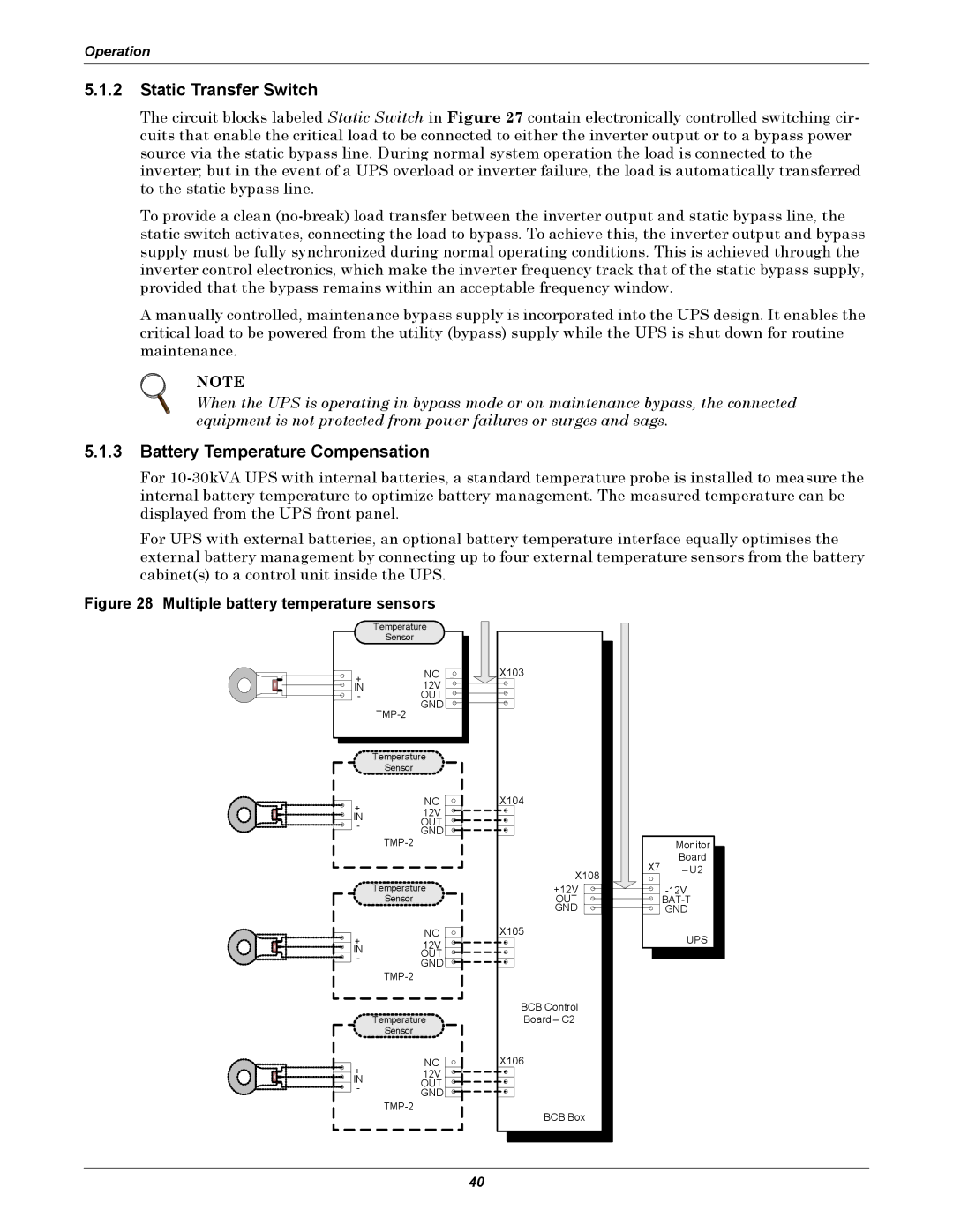
5.1.3Battery Temperature Compensation
For
For UPS with external batteries, an optional battery temperature interface equally optimises the external battery management by connecting up to four external temperature sensors from the battery cabinet(s) to a control unit inside the UPS.
Figure 28 Multiple battery temperature sensors
| Temperature | |
| Sensor | |
+ | NC | |
12V | ||
IN | ||
- | OUT | |
| GND | |
| ||
| Temperature | |
| Sensor | |
+ | NC | |
12V | ||
IN | ||
OUT | ||
- | ||
GND | ||
| ||
| Temperature | |
| Sensor | |
+ | NC | |
12V | ||
IN | ||
OUT | ||
- | ||
GND | ||
| ||
| ||
| Temperature | |
| Sensor | |
+ | NC | |
12V | ||
IN | OUT | |
- | ||
GND | ||
| ||
|
X103
X104
X108
+12V OUT GND
X105
BCB Control
Board – C2
X106
BCB Box
| Monitor |
X7 | Board |
– U2 |
UPS
40