Battery Installation
2.3.6Battery Temperature Sensor (Optional)
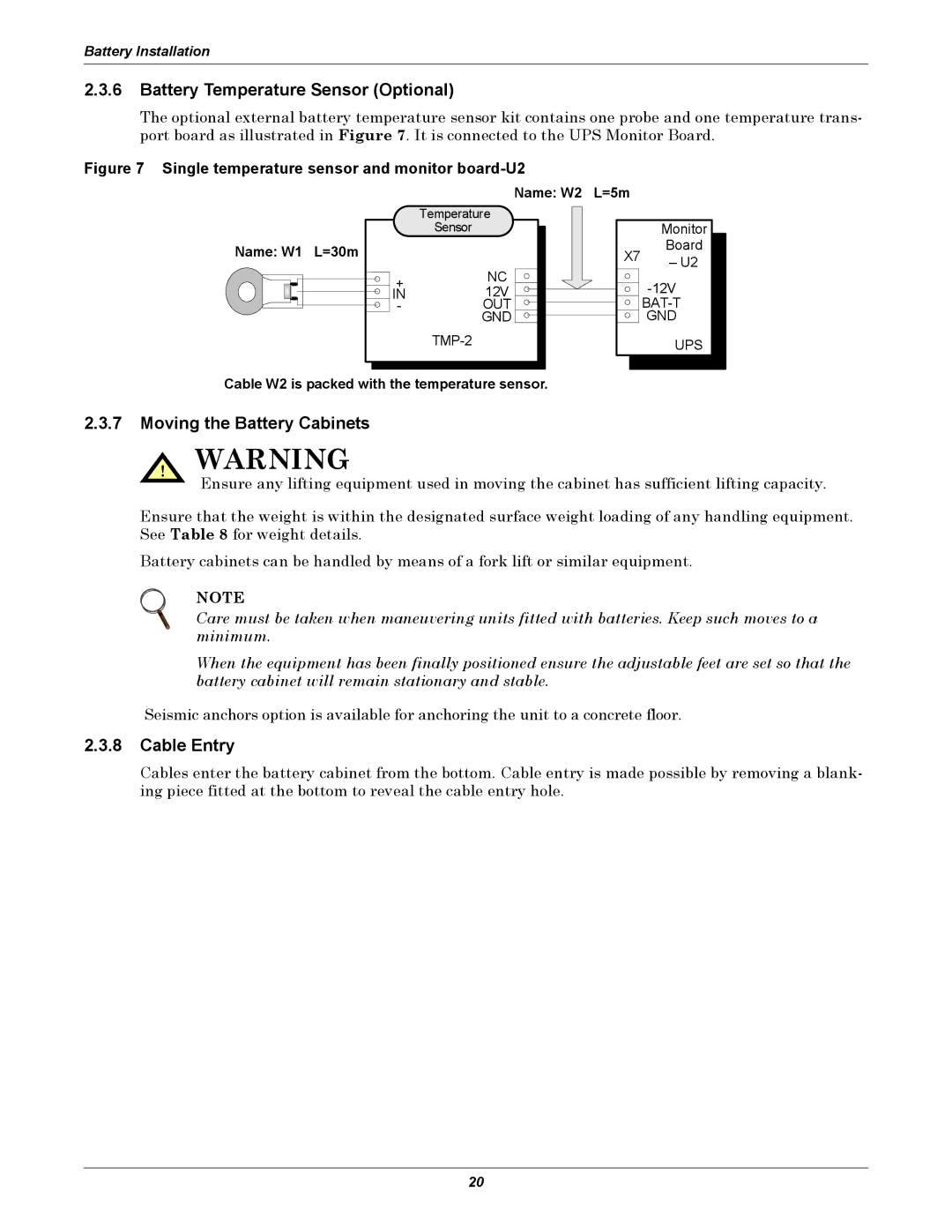
The optional external battery temperature sensor kit contains one probe and one temperature trans- port board as illustrated in Figure 7. It is connected to the UPS Monitor Board.
Figure 7 Single temperature sensor and monitor board-U2
Name: W2 L=5m
Name: W1 L=30m
Temperature
Sensor
+NC
IN12V
-OUT GND
Monitor
X7 | Board | |
– U2 | ||
|
UPS
Cable W2 is packed with the temperature sensor.
2.3.7Moving the Battery Cabinets
! WARNING
Ensure any lifting equipment used in moving the cabinet has sufficient lifting capacity.
Ensure that the weight is within the designated surface weight loading of any handling equipment. See Table 8 for weight details.
Battery cabinets can be handled by means of a fork lift or similar equipment.
NOTE
Care must be taken when maneuvering units fitted with batteries. Keep such moves to a minimum.
When the equipment has been finally positioned ensure the adjustable feet are set so that the battery cabinet will remain stationary and stable.
Seismic anchors option is available for anchoring the unit to a concrete floor.
2.3.8Cable Entry
Cables enter the battery cabinet from the bottom. Cable entry is made possible by removing a blank- ing piece fitted at the bottom to reveal the cable entry hole.
20