Single Module UPS Installation
1.8.3External Circuit-Breaker Interface
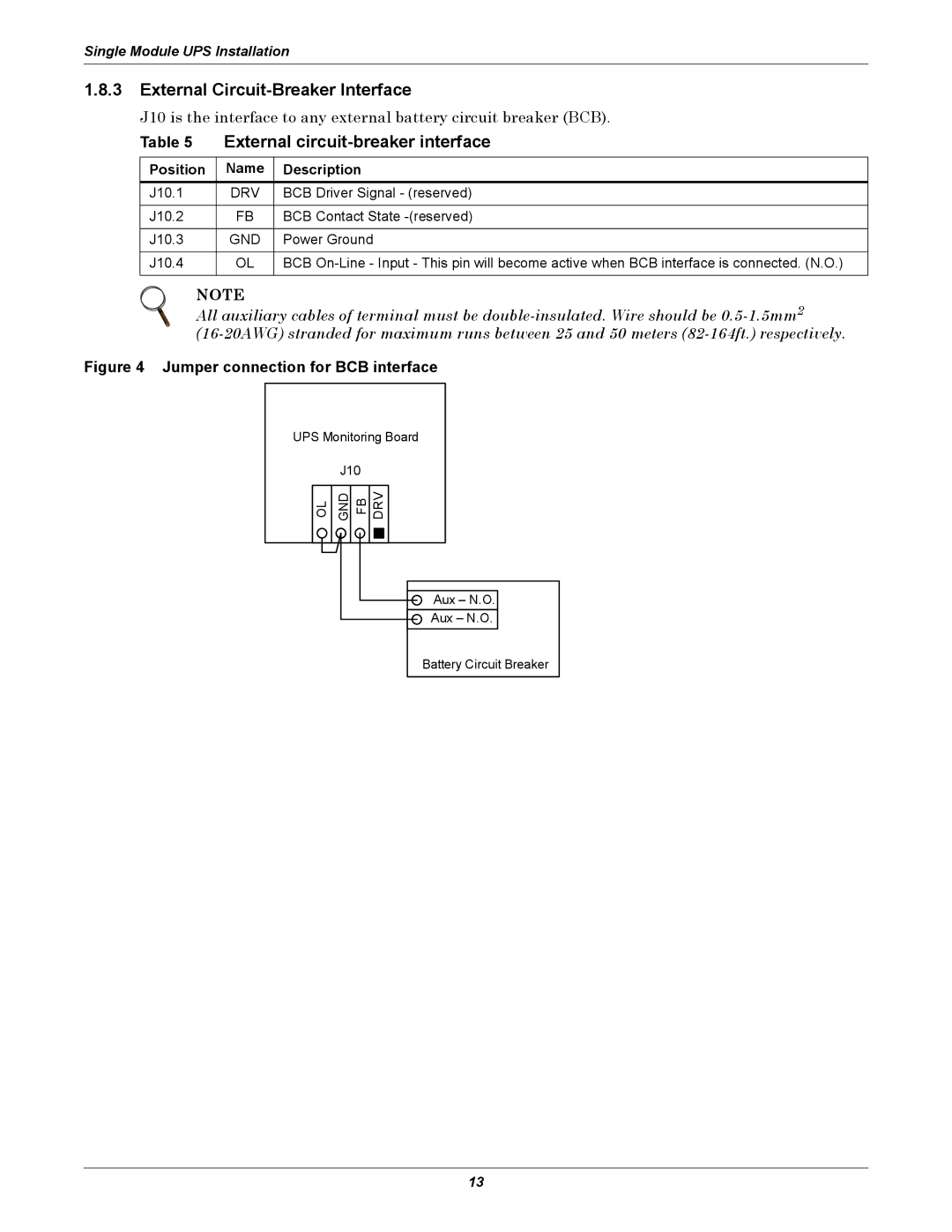
J10 is the interface to any external battery circuit breaker (BCB).
Table 5 External
Position | Name | Description |
J10.1 | DRV | BCB Driver Signal - (reserved) |
|
|
|
J10.2 | FB | BCB Contact State |
|
|
|
J10.3 | GND | Power Ground |
|
|
|
J10.4 | OL | BCB |
|
|
|
NOTE
All auxiliary cables of terminal must be
Figure 4 Jumper connection for BCB interface
UPS Monitoring Board
J10
OL
GND
FB
DRV
Aux – N.O.
Aux – N.O.
Battery Circuit Breaker
13