Installation Drawings
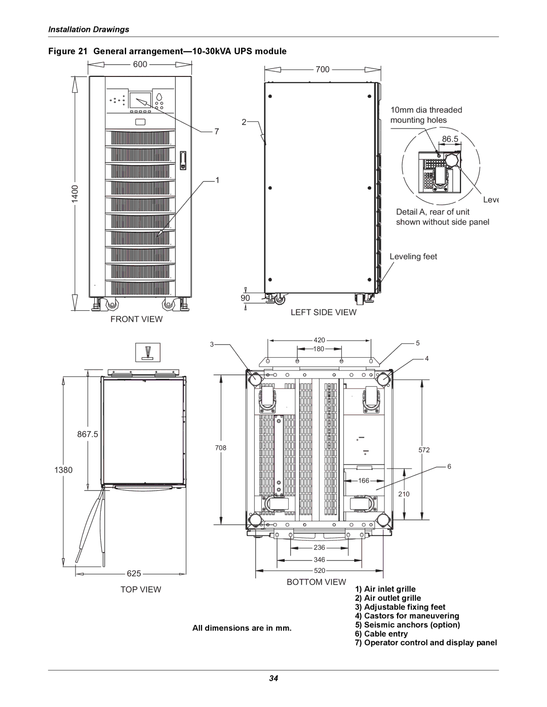
Figure 21 General arrangement—10-30kVA UPS module
600
700
2
7
1
1400
90
LEFT SIDE VIEW
FRONT VIEW
10mm dia threaded mounting holes
86.5
Leve
Detail A, rear of unit shown without side panel
Leveling feet
3
420
![]() 180
180 ![]()
![]()
5
4
867.5
1380
625
708
236
346
520
572
6
![]() 166
166 ![]()
210
TOP VIEW
BOTTOM VIEW 1) Air inlet grille
| 2) | Air outlet grille | |
| 3) | Adjustable fixing feet | |
| 4) | Castors for maneuvering | |
All dimensions are in mm. | 5) | Seismic anchors (option) | |
6) | Cable entry | ||
| |||
| 7) | Operator control and display panel |
34