Single Module UPS Installation
1.8Dry Contacts
The UPS provides input dry contacts and output dry contacts.
1.8.1Input Dry Contacts
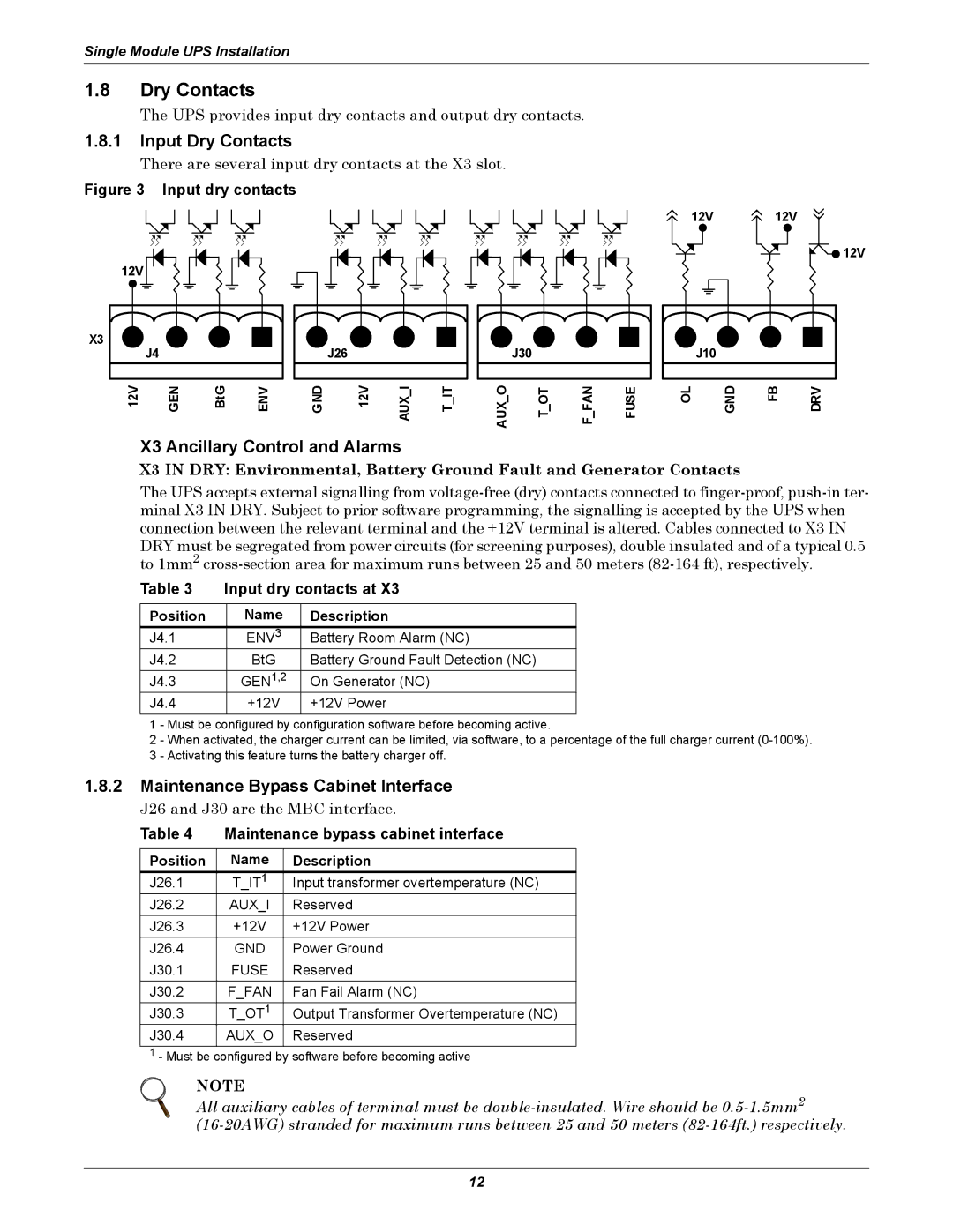
There are several input dry contacts at the X3 slot.
Figure 3 Input dry contacts
12V 12V
![]()
![]() 12V
12V
12V
X3
| J4 |
|
|
12V | GEN | BtG | ENV |
| J26 |
|
|
GND | 12V | AUX I | T IT |
| J30 |
|
|
AUX O | T OT | F FAN | FUSE |
J10
OL | GND | FB | DRV |
X3 Ancillary Control and Alarms
X3 IN DRY: Environmental, Battery Ground Fault and Generator Contacts
The UPS accepts external signalling from
Table 3 | Input dry contacts at X3 | ||
|
|
|
|
Position |
| Name | Description |
J4.1 |
| ENV3 | Battery Room Alarm (NC) |
J4.2 |
| BtG | Battery Ground Fault Detection (NC) |
J4.3 |
| GEN1,2 | On Generator (NO) |
J4.4 |
| +12V | +12V Power |
1 - Must be configured by configuration software before becoming active.
2 - When activated, the charger current can be limited, via software, to a percentage of the full charger current
1.8.2Maintenance Bypass Cabinet Interface
J26 and J30 are the MBC interface.
Table 4 Maintenance bypass cabinet interface
Position | Name | Description |
J26.1 | T_IT1 | Input transformer overtemperature (NC) |
J26.2 | AUX_I | Reserved |
J26.3 | +12V | +12V Power |
J26.4 | GND | Power Ground |
J30.1 | FUSE | Reserved |
J30.2 | F_FAN | Fan Fail Alarm (NC) |
J30.3 | T_OT1 | Output Transformer Overtemperature (NC) |
J30.4 | AUX_O | Reserved |
1- Must be configured by software before becoming active
NOTE
All auxiliary cables of terminal must be
12