TABLES
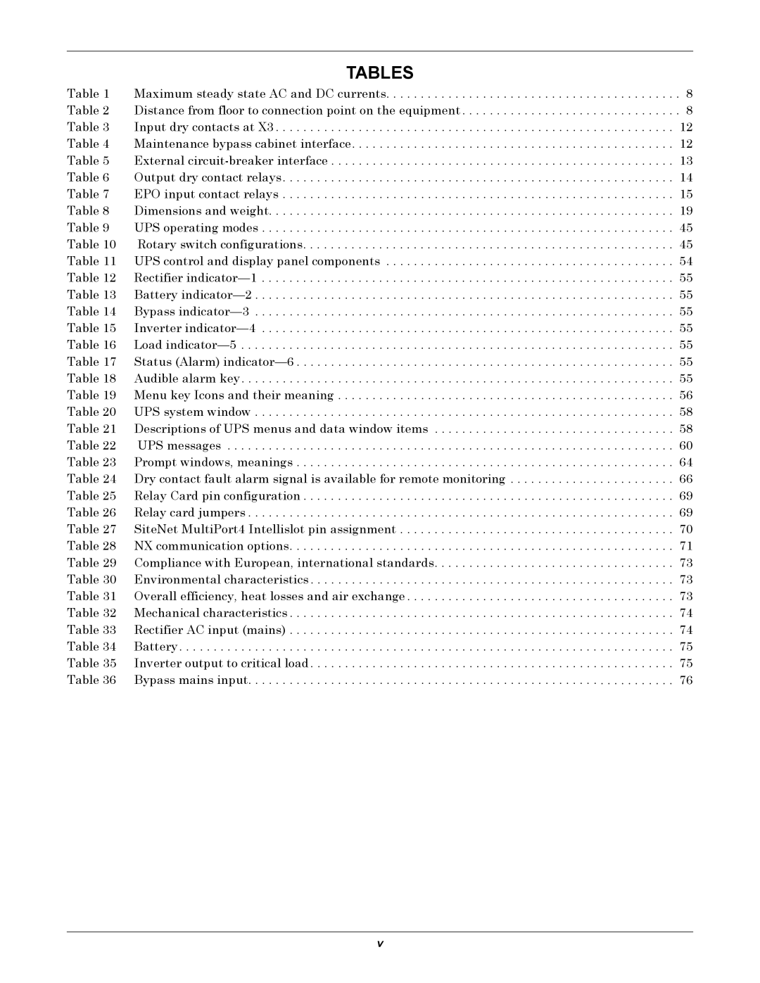
Table 1 Maximum steady state AC and DC currents. . . . . . . . . . . . . . . . . . . . . . . . . . . . . . . . . . . . . . . . . . . 8 Table 2 Distance from floor to connection point on the equipment . . . . . . . . . . . . . . . . . . . . . . . . . . . . . . . . 8 Table 3 Input dry contacts at X3 . . . . . . . . . . . . . . . . . . . . . . . . . . . . . . . . . . . . . . . . . . . . . . . . . . . . . . . . . . 12 Table 4 Maintenance bypass cabinet interface. . . . . . . . . . . . . . . . . . . . . . . . . . . . . . . . . . . . . . . . . . . . . . . 12 Table 5 External
v
