UPS
3.0UPS
3.1General
The installation of a
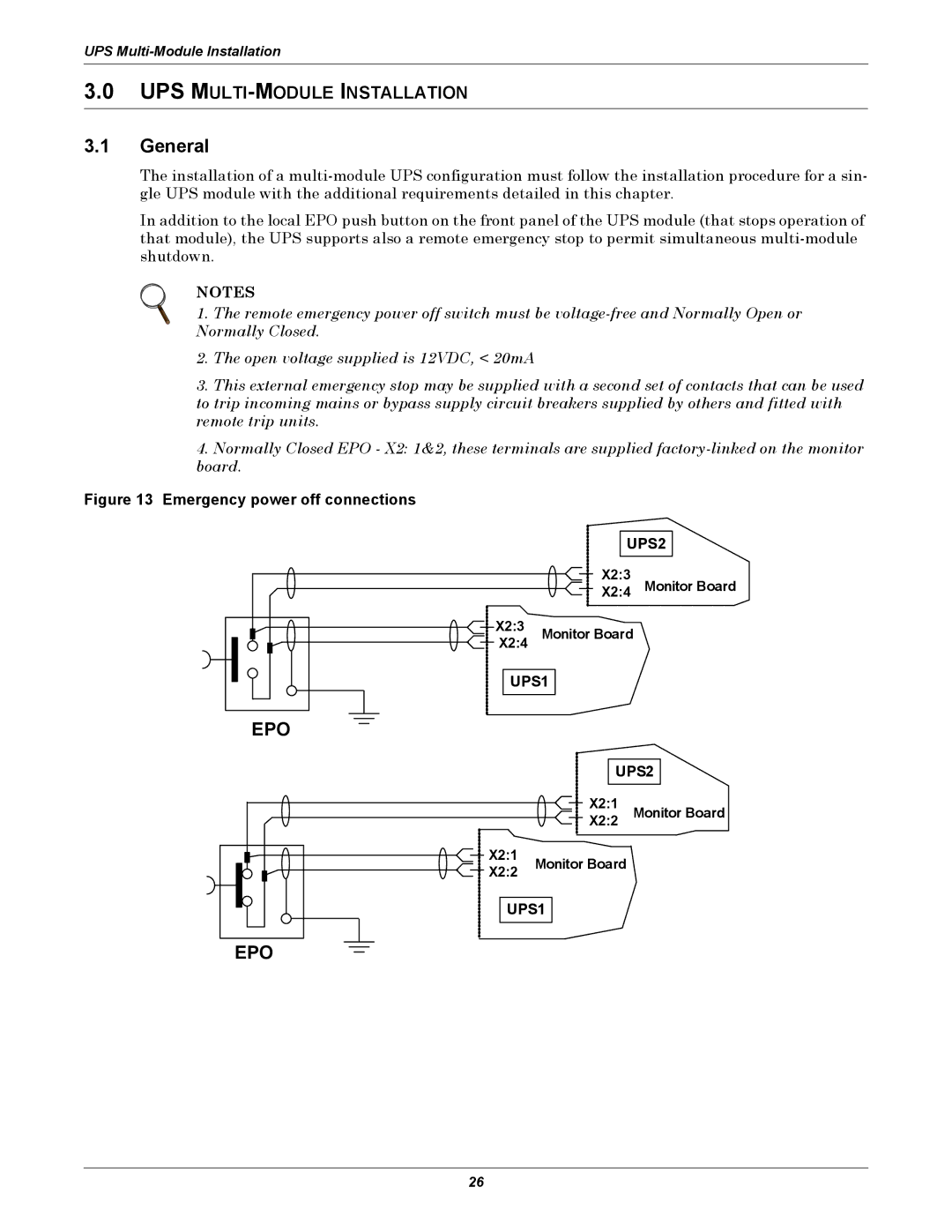
In addition to the local EPO push button on the front panel of the UPS module (that stops operation of that module), the UPS supports also a remote emergency stop to permit simultaneous
NOTES
1. The remote emergency power off switch must be
2.The open voltage supplied is 12VDC, < 20mA
3.This external emergency stop may be supplied with a second set of contacts that can be used to trip incoming mains or bypass supply circuit breakers supplied by others and fitted with remote trip units.
4.Normally Closed EPO - X2: 1&2, these terminals are supplied
Figure 13 Emergency power off connections
UPS2
X2:3
X2:4 Monitor Board
X2:3 | Monitor Board |
X2:4 |
UPS1
EPO
UPS2
X2:1 | Monitor Board |
X2:2 |
X2:1 | Monitor Board | |
X2:2 | ||
|
UPS1
EPO
26
