Operator Control Panel and Display
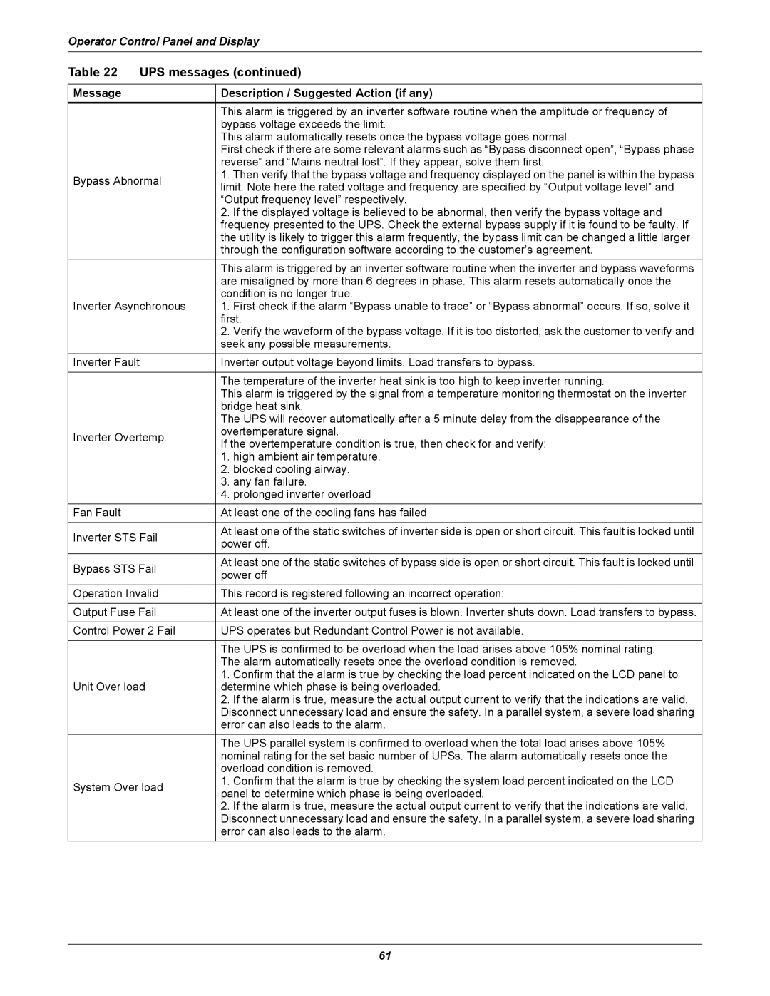
Table 22 | UPS messages (continued) | ||
|
|
| |
Message |
| Description / Suggested Action (if any) | |
|
| This alarm is triggered by an inverter software routine when the amplitude or frequency of | |
|
| bypass voltage exceeds the limit. | |
|
| This alarm automatically resets once the bypass voltage goes normal. | |
|
| First check if there are some relevant alarms such as “Bypass disconnect open”, “Bypass phase | |
|
| reverse” and “Mains neutral lost”. If they appear, solve them first. | |
Bypass Abnormal | 1. Then verify that the bypass voltage and frequency displayed on the panel is within the bypass | ||
limit. Note here the rated voltage and frequency are specified by “Output voltage level” and | |||
|
| ||
|
| “Output frequency level” respectively. | |
|
| 2. If the displayed voltage is believed to be abnormal, then verify the bypass voltage and | |
|
| frequency presented to the UPS. Check the external bypass supply if it is found to be faulty. If | |
|
| the utility is likely to trigger this alarm frequently, the bypass limit can be changed a little larger | |
|
| through the configuration software according to the customer’s agreement. | |
|
| This alarm is triggered by an inverter software routine when the inverter and bypass waveforms | |
|
| are misaligned by more than 6 degrees in phase. This alarm resets automatically once the | |
|
| condition is no longer true. | |
Inverter Asynchronous | 1. First check if the alarm “Bypass unable to trace” or “Bypass abnormal” occurs. If so, solve it | ||
|
| first. | |
|
| 2. Verify the waveform of the bypass voltage. If it is too distorted, ask the customer to verify and | |
|
| seek any possible measurements. | |
Inverter Fault | Inverter output voltage beyond limits. Load transfers to bypass. | ||
|
|
| |
|
| The temperature of the inverter heat sink is too high to keep inverter running. | |
|
| This alarm is triggered by the signal from a temperature monitoring thermostat on the inverter | |
|
| bridge heat sink. | |
|
| The UPS will recover automatically after a 5 minute delay from the disappearance of the | |
Inverter Overtemp. | overtemperature signal. | ||
If the overtemperature condition is true, then check for and verify: | |||
|
| ||
|
| 1. high ambient air temperature. | |
|
| 2. blocked cooling airway. | |
|
| 3. any fan failure. | |
|
| 4. prolonged inverter overload | |
Fan Fault |
| At least one of the cooling fans has failed | |
|
|
| |
Inverter STS Fail | At least one of the static switches of inverter side is open or short circuit. This fault is locked until | ||
power off. | |||
|
| ||
Bypass STS Fail | At least one of the static switches of bypass side is open or short circuit. This fault is locked until | ||
power off | |||
|
| ||
Operation Invalid | This record is registered following an incorrect operation: | ||
|
| ||
Output Fuse Fail | At least one of the inverter output fuses is blown. Inverter shuts down. Load transfers to bypass. | ||
|
| ||
Control Power 2 Fail | UPS operates but Redundant Control Power is not available. | ||
|
|
| |
|
| The UPS is confirmed to be overload when the load arises above 105% nominal rating. | |
|
| The alarm automatically resets once the overload condition is removed. | |
|
| 1. Confirm that the alarm is true by checking the load percent indicated on the LCD panel to | |
Unit Over load | determine which phase is being overloaded. | ||
|
| 2. If the alarm is true, measure the actual output current to verify that the indications are valid. | |
|
| Disconnect unnecessary load and ensure the safety. In a parallel system, a severe load sharing | |
|
| error can also leads to the alarm. | |
|
| The UPS parallel system is confirmed to overload when the total load arises above 105% | |
|
| nominal rating for the set basic number of UPSs. The alarm automatically resets once the | |
|
| overload condition is removed. | |
System Over load | 1. Confirm that the alarm is true by checking the system load percent indicated on the LCD | ||
panel to determine which phase is being overloaded. | |||
|
| ||
|
| 2. If the alarm is true, measure the actual output current to verify that the indications are valid. | |
|
| Disconnect unnecessary load and ensure the safety. In a parallel system, a severe load sharing | |
|
| error can also leads to the alarm. | |
61