Operator Control Panel and Display
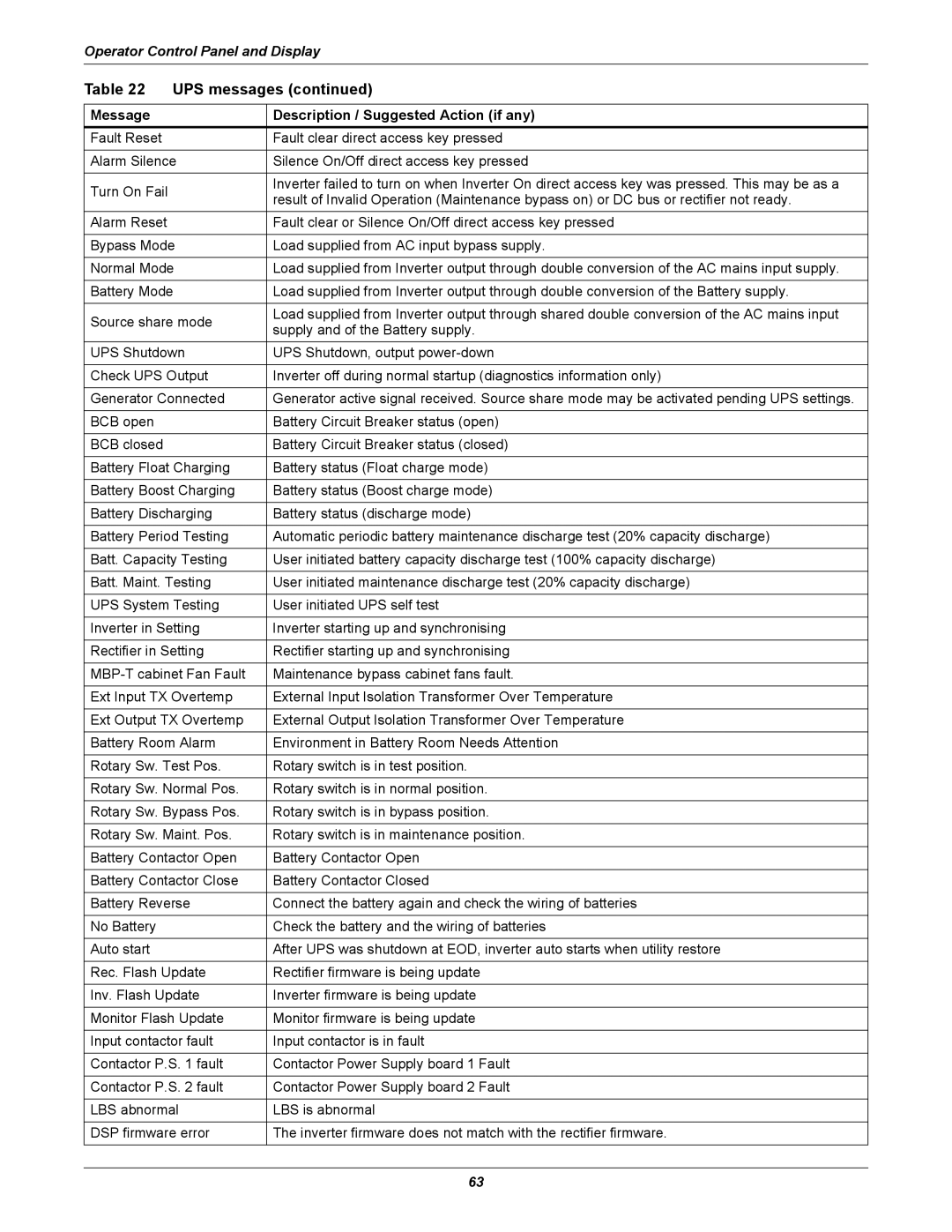
Table 22 | UPS messages (continued) | ||
|
|
| |
Message |
| Description / Suggested Action (if any) | |
Fault Reset |
| Fault clear direct access key pressed | |
|
| ||
Alarm Silence | Silence On/Off direct access key pressed | ||
|
|
| |
Turn On Fail |
| Inverter failed to turn on when Inverter On direct access key was pressed. This may be as a | |
| result of Invalid Operation (Maintenance bypass on) or DC bus or rectifier not ready. | ||
|
| ||
Alarm Reset |
| Fault clear or Silence On/Off direct access key pressed | |
|
| ||
Bypass Mode | Load supplied from AC input bypass supply. | ||
|
| ||
Normal Mode | Load supplied from Inverter output through double conversion of the AC mains input supply. | ||
|
| ||
Battery Mode | Load supplied from Inverter output through double conversion of the Battery supply. | ||
|
|
| |
Source share mode | Load supplied from Inverter output through shared double conversion of the AC mains input | ||
supply and of the Battery supply. | |||
|
| ||
UPS Shutdown | UPS Shutdown, output | ||
|
| ||
Check UPS Output | Inverter off during normal startup (diagnostics information only) | ||
|
| ||
Generator Connected | Generator active signal received. Source share mode may be activated pending UPS settings. | ||
|
|
| |
BCB open |
| Battery Circuit Breaker status (open) | |
|
|
| |
BCB closed |
| Battery Circuit Breaker status (closed) | |
|
| ||
Battery Float Charging | Battery status (Float charge mode) | ||
|
| ||
Battery Boost Charging | Battery status (Boost charge mode) | ||
|
| ||
Battery Discharging | Battery status (discharge mode) | ||
|
| ||
Battery Period Testing | Automatic periodic battery maintenance discharge test (20% capacity discharge) | ||
|
| ||
Batt. Capacity Testing | User initiated battery capacity discharge test (100% capacity discharge) | ||
|
| ||
Batt. Maint. Testing | User initiated maintenance discharge test (20% capacity discharge) | ||
|
| ||
UPS System Testing | User initiated UPS self test | ||
|
| ||
Inverter in Setting | Inverter starting up and synchronising | ||
|
| ||
Rectifier in Setting | Rectifier starting up and synchronising | ||
|
| ||
Maintenance bypass cabinet fans fault. | |||
|
| ||
Ext Input TX Overtemp | External Input Isolation Transformer Over Temperature | ||
|
| ||
Ext Output TX Overtemp | External Output Isolation Transformer Over Temperature | ||
|
| ||
Battery Room Alarm | Environment in Battery Room Needs Attention | ||
|
| ||
Rotary Sw. Test Pos. | Rotary switch is in test position. | ||
|
| ||
Rotary Sw. Normal Pos. | Rotary switch is in normal position. | ||
|
| ||
Rotary Sw. Bypass Pos. | Rotary switch is in bypass position. | ||
|
| ||
Rotary Sw. Maint. Pos. | Rotary switch is in maintenance position. | ||
|
| ||
Battery Contactor Open | Battery Contactor Open | ||
|
| ||
Battery Contactor Close | Battery Contactor Closed | ||
|
| ||
Battery Reverse | Connect the battery again and check the wiring of batteries | ||
|
|
| |
No Battery |
| Check the battery and the wiring of batteries | |
|
|
| |
Auto start |
| After UPS was shutdown at EOD, inverter auto starts when utility restore | |
|
| ||
Rec. Flash Update | Rectifier firmware is being update | ||
|
| ||
Inv. Flash Update | Inverter firmware is being update | ||
|
| ||
Monitor Flash Update | Monitor firmware is being update | ||
|
| ||
Input contactor fault | Input contactor is in fault | ||
|
| ||
Contactor P.S. 1 fault | Contactor Power Supply board 1 Fault | ||
|
| ||
Contactor P.S. 2 fault | Contactor Power Supply board 2 Fault | ||
|
| ||
LBS abnormal | LBS is abnormal | ||
|
| ||
DSP firmware error | The inverter firmware does not match with the rectifier firmware. | ||
|
|
| |
63