Battery Installation
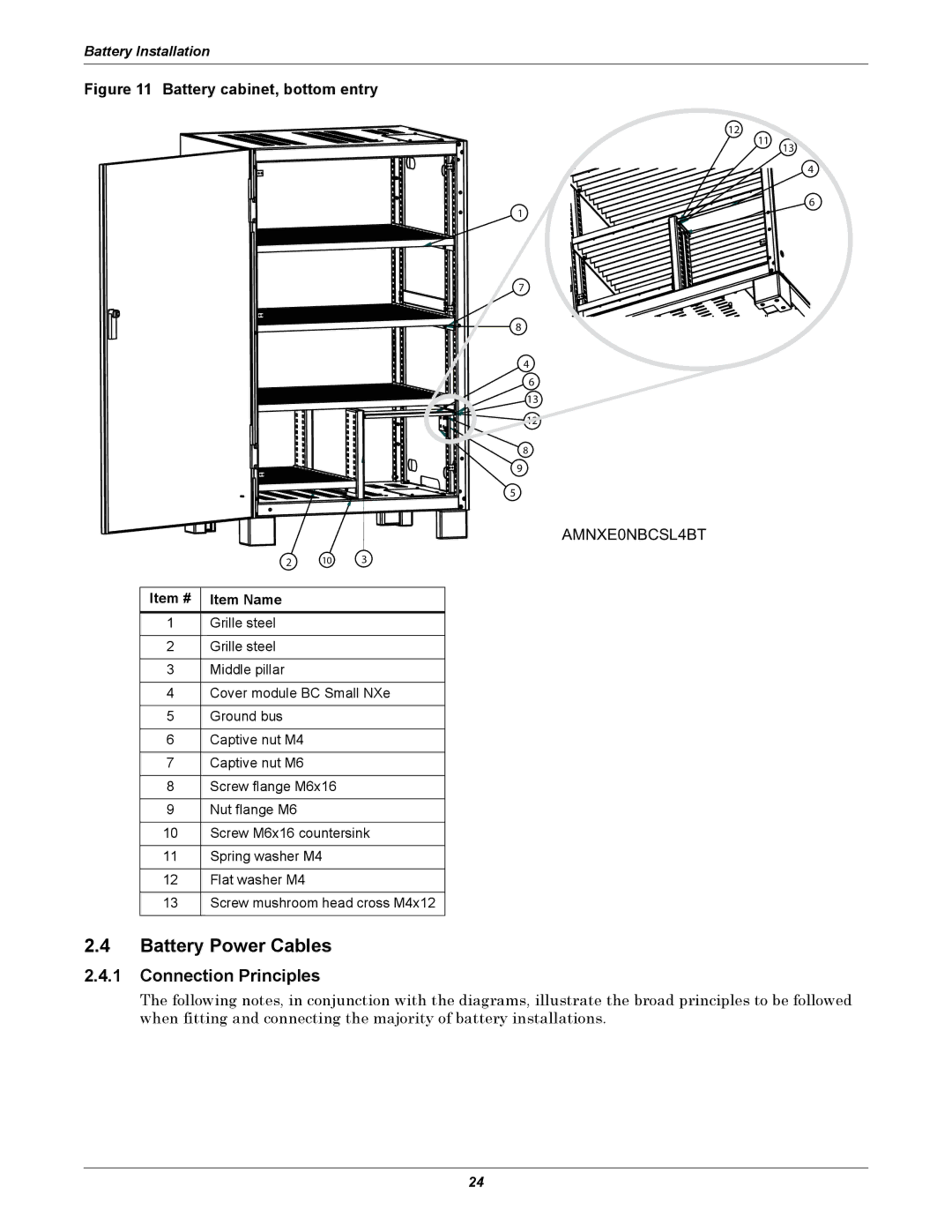
Figure 11 Battery cabinet, bottom entry
12
11
1
7
8
4
6
13
![]() 12
12
8
9
5
AMNXE0NBCSL4BT
| 2 | 10 | 3 |
|
|
|
|
Item # | Item Name |
|
|
|
|
|
|
1 | Grille steel |
|
|
|
|
|
|
2 | Grille steel |
|
|
|
|
|
|
3 | Middle pillar |
|
|
|
| ||
4 | Cover module BC Small NXe | ||
|
|
|
|
5 | Ground bus |
|
|
|
|
|
|
6 | Captive nut M4 |
|
|
|
|
|
|
7 | Captive nut M6 |
|
|
|
|
| |
8 | Screw flange M6x16 |
| |
|
|
|
|
9 | Nut flange M6 |
|
|
|
| ||
10 | Screw M6x16 countersink | ||
|
|
| |
11 | Spring washer M4 |
| |
|
|
|
|
12 | Flat washer M4 |
|
|
|
| ||
13 | Screw mushroom head cross M4x12 | ||
|
|
|
|
2.4Battery Power Cables
13
4
6
2.4.1Connection Principles
The following notes, in conjunction with the diagrams, illustrate the broad principles to be followed when fitting and connecting the majority of battery installations.
24