UPS
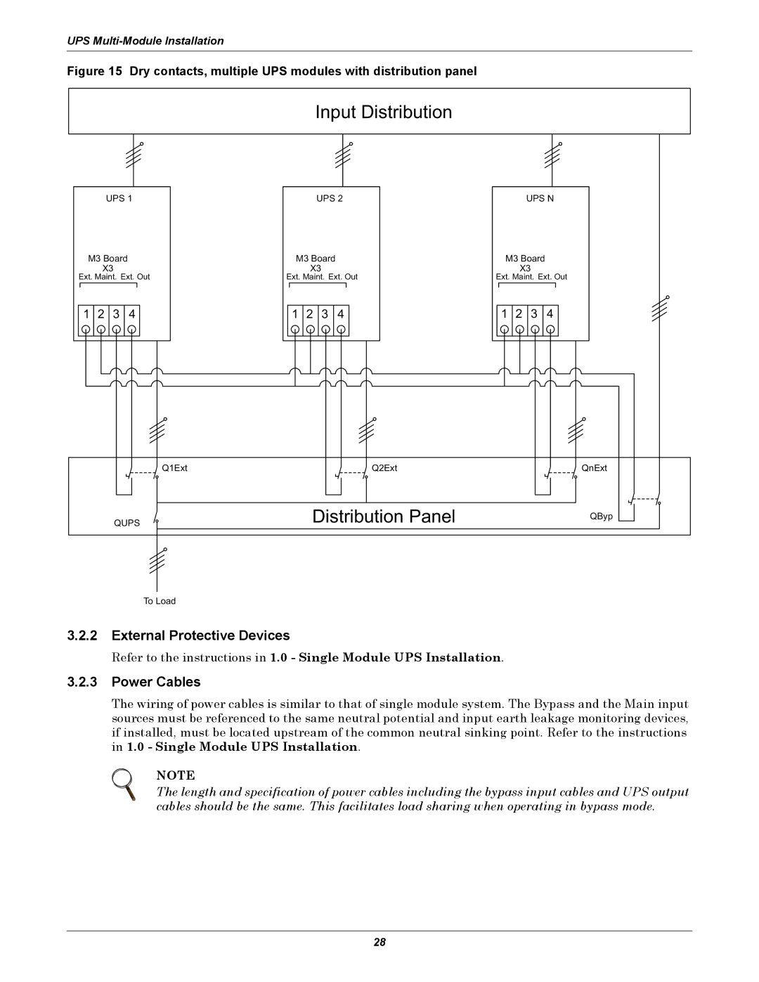
Figure 15 Dry contacts, multiple UPS modules with distribution panel
Input Distribution
UPS 1 | UPS 2 | UPS N |
M3 Board | M3 Board | M3 Board |
X3 | X3 | X3 |
Ext. Maint. Ext. Out | Ext. Maint. Ext. Out | Ext. Maint. Ext. Out |
1 | 2 | 3 | 4 | 1 | 2 | 3 | 4 | 1 | 2 | 3 | 4 |
Q1ExtQ2ExtQnExt
QUPS | Distribution Panel | QByp |
|
|
To Load
3.2.2External Protective Devices
Refer to the instructions in 1.0 - Single Module UPS Installation.
3.2.3Power Cables
The wiring of power cables is similar to that of single module system. The Bypass and the Main input sources must be referenced to the same neutral potential and input earth leakage monitoring devices, if installed, must be located upstream of the common neutral sinking point. Refer to the instructions in 1.0 - Single Module UPS Installation.
NOTE
The length and specification of power cables including the bypass input cables and UPS output cables should be the same. This facilitates load sharing when operating in bypass mode.
28