Operation
5.1.4Redundant Control Power Supply Board
The UPS is equipped with two identical and fully redundant control power supply boards. Each of them takes inputs from the AC and DC sources. When one of the sources or even if one of the control power boards fails, the UPS system can still operate normally. This feature further enhances the reli- ability of the system.
5.1.5Socket Outlet
One
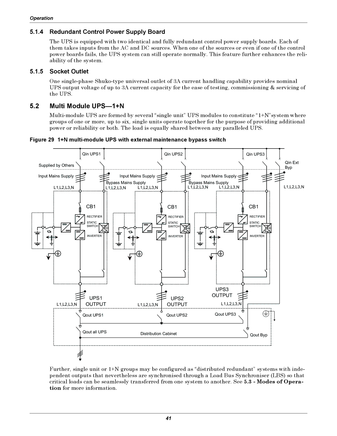
5.2Multi Module UPS—1+N
Figure 29 1+N multi-module UPS with external maintenance bypass switch
Qin UPS1
Supplied by Others
Input Mains Supply ![]()
L1,L2,L3,N
Qin UPS2
Input Mains Supply ![]()
Bypass Mains Supply
L1,L2,L3,N L1,L2,L3,N
Qin UPS3
Input Mains Supply ![]()
Bypass Mains Supply
L1,L2,L3,N L1,L2,L3,N
Qin Ext
Byp
L1,L2,L3,N
CB1
RECTIFIER
STATIC
SWITCH
INVERTER
UPS1
L1,L2,L3,N OUTPUT
Qout UPS1
![]() Qout all UPS
Qout all UPS
CB1
RECTIFIER
STATIC
SWITCH
INVERTER
UPS2
L1,L2,L3,N OUTPUT
Qout UPS2
Distribution Cabinet
CB1
RECTIFIER
STATIC
SWITCH
INVERTER
UPS3
OUTPUT
L1,L2,L3,N
Qout UPS3
Qout Byp
Further, single unit or 1+N groups may be configured as “distributed redundant” systems with inde- pendent outputs that nevertheless are synchronised through a Load Bus Synchroniser (LBS) so that critical loads can be seamlessly transferred from one system to another. See 5.3 - Modes of Opera- tion for more information.
41