
RS232 specifications
Star Micronics RS232 is a versatile and widely used connectivity standard that enables seamless communication between peripheral devices and computers, particularly in point-of-sale (POS) environments. This technology is renowned for its robustness and reliability, making it a preferred choice for businesses in various sectors, including retail, hospitality, and healthcare.One of the main features of Star Micronics RS232 is its ability to facilitate serial communication, allowing devices to exchange data one bit at a time over a single communication line. This enables simple and effective connections between devices like printers, cash registers, and barcode scanners. The standard typically operates at data rates ranging from 300 to 115200 bits per second, accommodating various application needs.
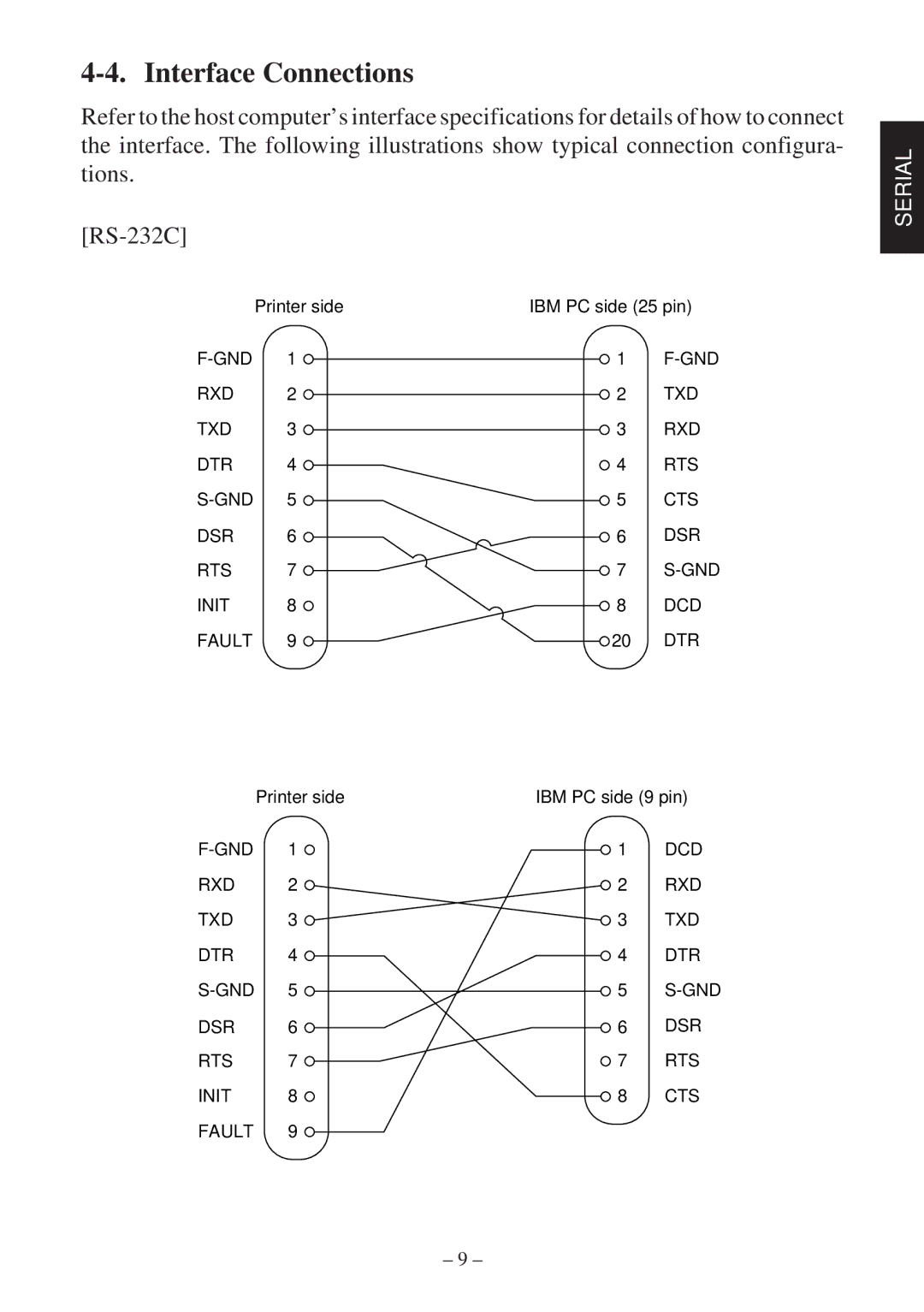
The RS232 interface is characterized by its 9-pin (DB9) or 25-pin (DB25) connectors, with the DB9 being the more commonly used in modern applications. It provides a straightforward plug-and-play experience, allowing devices to be easily connected and configured without extensive technical knowledge. This simplicity is particularly beneficial for retail staff who may not possess in-depth IT expertise.
Another significant aspect of RS232 technology is its point-to-point architecture. This means each connected device operates independently, enhancing overall system performance. Moreover, RS232 supports long-distance communication, with the ability to transmit data over cable lengths of up to 50 feet (15 meters), which is advantageous in larger retail settings.
In terms of compatibility, Star Micronics RS232 devices are designed to work seamlessly with various operating systems, including Windows, macOS, and Linux. This widespread compatibility ensures that businesses can continue to leverage their existing infrastructure without the need for costly upgrades.
Additionally, Star Micronics has incorporated advanced technologies into their RS232 products, such as built-in error checking and data control features. These enhancements help minimize data transmission errors and ensure that the information exchanged between devices remains accurate and reliable.
In summary, Star Micronics RS232 offers a robust set of features, including simple connectivity, point-to-point architecture, and compatibility with various systems. Its proven performance and reliability make it a trusted choice for businesses looking to enhance their operational efficiency and streamline their processes. As POS technology continues to evolve, the Star Micronics RS232 standard remains a foundational component for effective device communication.