cont.


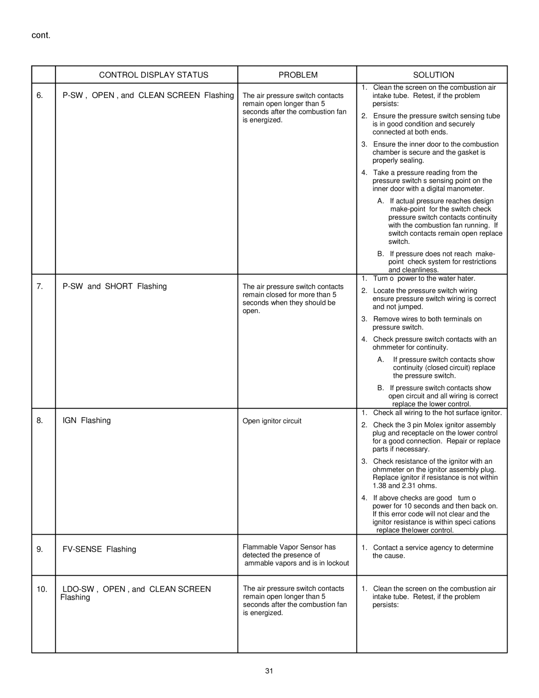
CONTROL DISPLAY STATUS

PROBLEM


SOLUTION


6.

“P-SW”, “OPEN”, and “CLEAN SCREEN” Flashing


1.

Clean the screen on the combustion air

The air pressure switch contacts


intake tube. Retest, if the problem


remain open longer than 5


persists:


seconds after the combustion fan

2.

Ensure the pressure switch sensing tube


is energized.


is in good condition and securely


connected at both ends.


3.

Ensure the inner door to the combustion


chamber is secure and the gasket is


properly sealing.


4.

Take a pressure reading from the


pressure switch’s sensing point on the


inner door with a digital manometer.


A. If actual pressure reaches design


“make-point” for the switch check


pressure switch contacts continuity


with the combustion fan running. If


switch contacts remain open replace


switch.


B. If pressure does not reach “make-


point” check system for restrictions


and cleanliness.

7.

“P-SW” and “SHORT” Flashing

The air pressure switch contacts

1.

Turn off power to the water hater.

2.

Locate the pressure switch wiring –


remain closed for more than 5


ensure pressure switch wiring is correct


seconds when they should be


and not jumped.


open.


3.

Remove wires to both terminals on


pressure switch.


4.

Check pressure switch contacts with an


ohmmeter for continuity.


A. If pressure switch contacts show


continuity (closed circuit) replace


the pressure switch.


B. If pressure switch contacts show


open circuit and all wiring is correct


– replace the lower control.

8.

“IGN” Flashing

Open ignitor circuit

1.

Check all wiring to the hot surface ignitor.

2.

Check the 3 pin Molex ignitor assembly


plug and receptacle on the lower control


for a good connection. Repair or replace


parts if necessary.


3.

Check resistance of the ignitor with an


ohmmeter on the ignitor assembly plug.


Replace ignitor if resistance is not within


1.38 and 2.31 ohms.


4.

If above checks are good – turn off


power for 10 seconds and then back on.


If this error code will not clear and the


ignitor resistance is within specifications


– replace the lower control.

9.

“FV-SENSE” Flashing

Flammable Vapor Sensor has

1.

Contact a service agency to determine


detected the presence of


the cause.


flammable vapors and is in lockout


10.

“LDO-SW”, “OPEN”, and “CLEAN SCREEN”

The air pressure switch contacts

1.

Clean the screen on the combustion air


Flashing

remain open longer than 5


intake tube. Retest, if the problem


seconds after the combustion fan


persists:


is energized.


31

Page 31
Image 31
State Industries GP 6 40YPC T 100, GP 6 50YPC T 100, 317998-002 Control Display Status Problem Solution

317998-002, GP 6 50YPC T 100, GP 6 40YPC T 100 specifications

State Industries has long been at the forefront of technological advancements and innovative design in the industrial market. The company has developed a range of high-efficiency products designed for various applications, including the GP 6 40YPC T 100 and GP 6 50YPC T 100 models, as well as the 317998-002 component. Each product in this lineup is characterized by specific features and cutting-edge technologies tailored to meet diverse operational needs.

The GP 6 40YPC T 100 model boasts a robust construction aimed at durability and resilience in demanding environments. Its design incorporates advanced materials that resist wear and corrosion, ensuring a prolonged lifespan and reduced maintenance requirements. The model operates efficiently even in high-pressure scenarios, making it suitable for various industrial applications, including manufacturing and processing.

In contrast, the GP 6 50YPC T 100 model is designed with a focus on maximizing performance and energy efficiency. It features an optimized airflow system that enhances heat dissipation, preventing overheating and maintaining operational integrity. This model is ideal for applications that require continuous operation, as it minimizes downtime and maximizes productivity. Additionally, the GP 6 50YPC T 100 is equipped with smart technology that monitors performance metrics, providing real-time feedback on operational efficiency.

The 317998-002 component serves as a critical element in both models, acting as a versatile interface that integrates seamlessly with existing systems. It is designed to enhance connectivity and facilitate communication between various industrial components, promoting improved efficiency and ease of integration.

Both the GP 6 models and the 317998-002 feature user-friendly interfaces, allowing operators to easily manage and adjust settings. This focus on user experience helps to reduce training time and improve overall operational efficiency. Furthermore, both models adhere to strict industry standards, ensuring reliability and safety in all conditions.

In summary, State Industries' GP 6 40YPC T 100 and GP 6 50YPC T 100 models, along with the 317998-002 component, represent the pinnacle of innovation and reliability in industrial solutions. Their advanced features, technologies, and characteristics make them suitable choices for organizations looking to enhance productivity and operational efficiency in a variety of applications. With a commitment to quality and performance, State Industries continues to set the standard for excellence in the industry.