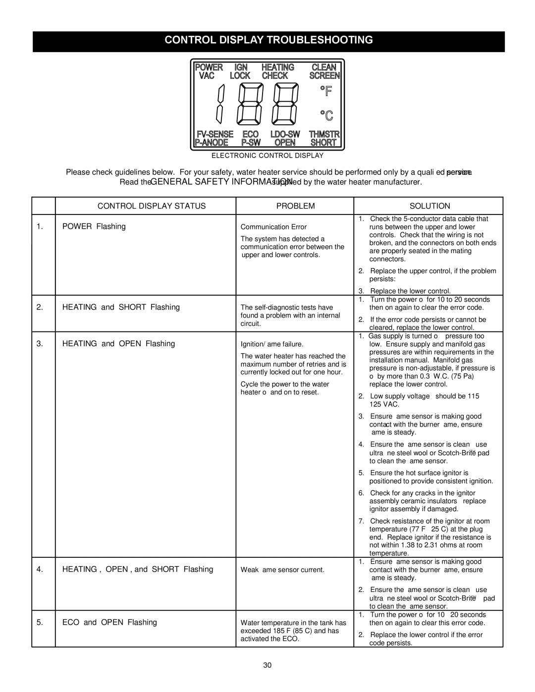
CONTROL DISPLAY TROUBLESHOOTING

ELECTRONIC CONTROL DISPLAY

Please check guidelines below. For your safety, water heater service should be performed only by a qualified service person.

Read the GENERAL SAFETY INFORMATION supplied by the water heater manufacturer.


CONTROL DISPLAY STATUS

PROBLEM


SOLUTION


1.

“POWER” Flashing


1.

Check the 5-conductor data cable that

Communication Error


runs between the upper and lower


The system has detected a


controls. Check that the wiring is not


broken, and the connectors on both ends


communication error between the


are properly seated in the mating


upper and lower controls.


connectors.


2.

Replace the upper control, if the problem


persists:


3.

Replace the lower control.

2.

“HEATING” and “SHORT” Flashing


1.

Turn the power off for 10 to 20 seconds

The self-diagnostic tests have


then on again to clear the error code.


found a problem with an internal

2.

If the error code persists or cannot be


circuit.


cleared, replace the lower control.


3.

“HEATING” and “OPEN” Flashing


1.

Gas supply is turned off – pressure too

Ignition/flame failure.


low. Ensure supply and manifold gas


The water heater has reached the


pressures are within requirements in the


installation manual. Manifold gas


maximum number of retries and is


pressure is non-adjustable, if pressure is


currently locked out for one hour.


off by more than 0.3” W.C. (75 Pa)


Cycle the power to the water


replace the lower control.


heater off and on to reset.

2.

Low supply voltage – should be 115 –


125 VAC.


3.

Ensure flame sensor is making good


contact with the burner flame, ensure


flame is steady.


4.

Ensure the flame sensor is clean – use


ultra fine steel wool or Scotch-BriteTMpad


to clean the flame sensor.


5.

Ensure the hot surface ignitor is


positioned to provide consistent ignition.


6.

Check for any cracks in the ignitor


assembly ceramic insulators – replace


ignitor assembly if damaged.


7.

Check resistance of the ignitor at room


temperature (77°F – 25°C) at the plug


end. Replace ignitor if the resistance is


not within 1.38 to 2.31 ohms at room


temperature.

4.

“HEATING”, “OPEN”, and “SHORT” Flashing


1.

Ensure flame sensor is making good

Weak flame sensor current.


contact with the burner flame, ensure


flame is steady.


2.

Ensure the flame sensor is clean – use


ultra fine steel wool or Scotch-BriteTMpad


to clean the flame sensor.

5.

“ECO” and “OPEN” Flashing


1.

Turn the power off for 10 – 20 seconds

Water temperature in the tank has


then on again to clear this error code.


exceeded 185°F (85°C) and has

2.

Replace the lower control if the error


activated the ECO.


code persists.


30

Page 30
Image 30
State Industries GP 6 50YPC T 100, 317998-002 Control Display Troubleshooting, Control Display Status Problem Solution

317998-002, GP 6 50YPC T 100, GP 6 40YPC T 100 specifications

State Industries has long been at the forefront of technological advancements and innovative design in the industrial market. The company has developed a range of high-efficiency products designed for various applications, including the GP 6 40YPC T 100 and GP 6 50YPC T 100 models, as well as the 317998-002 component. Each product in this lineup is characterized by specific features and cutting-edge technologies tailored to meet diverse operational needs.

The GP 6 40YPC T 100 model boasts a robust construction aimed at durability and resilience in demanding environments. Its design incorporates advanced materials that resist wear and corrosion, ensuring a prolonged lifespan and reduced maintenance requirements. The model operates efficiently even in high-pressure scenarios, making it suitable for various industrial applications, including manufacturing and processing.

In contrast, the GP 6 50YPC T 100 model is designed with a focus on maximizing performance and energy efficiency. It features an optimized airflow system that enhances heat dissipation, preventing overheating and maintaining operational integrity. This model is ideal for applications that require continuous operation, as it minimizes downtime and maximizes productivity. Additionally, the GP 6 50YPC T 100 is equipped with smart technology that monitors performance metrics, providing real-time feedback on operational efficiency.

The 317998-002 component serves as a critical element in both models, acting as a versatile interface that integrates seamlessly with existing systems. It is designed to enhance connectivity and facilitate communication between various industrial components, promoting improved efficiency and ease of integration.

Both the GP 6 models and the 317998-002 feature user-friendly interfaces, allowing operators to easily manage and adjust settings. This focus on user experience helps to reduce training time and improve overall operational efficiency. Furthermore, both models adhere to strict industry standards, ensuring reliability and safety in all conditions.

In summary, State Industries' GP 6 40YPC T 100 and GP 6 50YPC T 100 models, along with the 317998-002 component, represent the pinnacle of innovation and reliability in industrial solutions. Their advanced features, technologies, and characteristics make them suitable choices for organizations looking to enhance productivity and operational efficiency in a variety of applications. With a commitment to quality and performance, State Industries continues to set the standard for excellence in the industry.