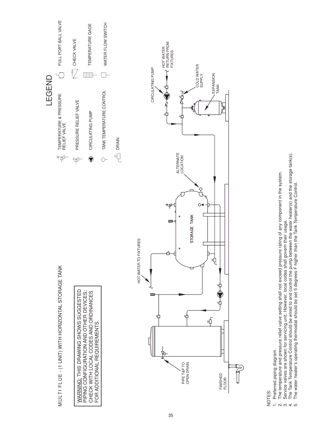
MULTI FLUE - (1 UNIT) WITH HORIZONTAL STORAGE TANK
WARNING: THIS DRAWING SHOWS SUGGESTED
PIPING CONFIGURATION AND OTHER DEVICES;
CHECK WITH LOCAL CODES AND ORDINANCES
FOR ADDITIONAL REQUIREMENTS.
HOT WATER TO FIXTURES
35
PIPE T&P TO
OPEN DRAIN
FINISHED
FLOOR
LEGEND
TEMPERATURE & PRESSURE | FULL PORT BALL VALVE |
RELIEF VALVE |
|
PRESSURE RELIEF VALVE | CHECK VALVE |
| |
CIRCULATING PUMP | TEMPERATURE GAGE |
TANK TEMPERATURE CONTROL | WATER FLOW SWITCH |
| |
DRAIN |
|
CIRCULATING PUMP
HOT WATER
RETURN FROM FIXTURES
ALTERNATE
LOCATION
COLD WATER
SUPPLY
![]() EXPANSION
EXPANSION
TANK
NOTES:
1.Preferred piping diagram.
2.The temperature and pressure relief valve setting shall not exceed pressure rating of any component in the system.
3.Service valves are shown for servicing unit. However, local codes shall govern their usage.
4.The Tank Temperature Control should be wired to and control the pump between the water heater(s) and the storage tank(s).
5.The water heater’s operating thermostat should be set 5 degrees F higher than the Tank Temperature Control.