Start up
Prior to Start Up
Installation and start up of this water heater requires abilities and skills equivalent to that of a licensed tradesman in the field involved, see Qualifications on page 6.
Do not place the water heater in operation if any part has been under water. Immediately call a qualified service technician to inspect the water heater and to replace any part of the control system and any gas control which has been under water.
Light the water heater in accordance with the Lighting and Operation Instruction label on the water heater and in this manual on page 26.
The water heaters covered by this manual are equipped with an electronic control system that automatically sequences the Blower, the Igniter, the 24 VAC Gas Valve, Burner ignition, and flame sensing. The control system will lock out after three unsuccessful ignition attempts.
Before attempting start up, thoroughly study and familiarize yourself with the exact Sequence Of Operation, see the written Sequence Of Operation on page 26 and the Sequence Of Operation Flow Chart on page 27.
Be certain that the water heater is full of water, that air is purged from the gas and water lines and that there are no leaks in the gas and water lines. Ensure all inlet water valves are open.
Filling The Water Heater
Follow these steps to fill the water heater prior to start up.
1.Close the heater drain valve.
2.Open a nearby hot water faucet to permit the air in the system to escape.
3.Fully open the cold water inlet valve allowing the piping and water heater to fill with water.
4.Close the hot water faucet opened in Step 2 as water starts to flow.
Supply Gas Line Purging
Fire or Explosion Hazard
Gas line purging is required with new piping or systems in which air has entered.
To avoid risk of fire or explosion purge discharge must not enter into confined areas or spaces where ignition can occur.
The area must be well ventilated and all sources of ignition must be deactivated or removed.
Use only the gas shown on the water heater rating label.
Keep ignition sources away from faucets after extended periods of
Read instruction manual before
installing, using or servicing
water heater.
1.Close the Main Gas Shutoff Valve, see Figure 21 on page 23.
2.Purge all air from the supply gas line up to the water heater’s Main Gas Shutoff Valve.
3.When all air has been purged from the supply gas line, tighten all supply gas line connections.
4.Check for gas leaks, see Gas Line Leak Testing on page 23 and repair any leaks found.
Initial Start Up
Required Test Equipment
Note: All test equipment must be acclimated to ambient temperature before calibration and use.
Preparation
1.Adjust the thermostat to the lowest temperature setting.
2.Turn the water heater’s on/off switch to the “off” position.
3.Close the Main Gas Shut Off Valve, see Figure 21 on page 23.
4.Wait five (5) minutes for any residual gas to clear.
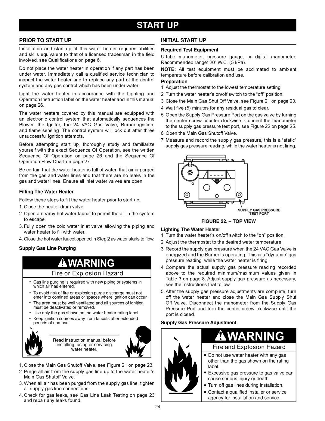
5.Open the Supply Gas Pressure Port on the gas valve by turning the center screw
6.Open the Main Gas Shutoff Valve.
7.Measure and record the supply gas pressure, this is a “static” supply gas pressure reading; while the water heater is not firing.
Figure 22. – Top View
Lighting The Water Heater
1.Turn the water heater’s on/off switch to the “on” position.
2.Adjust the thermostat to the desired water temperature.
3.Record the supply gas pressure when the 24 VAC Gas Valve is energized and the Burner is operating. This is a “dynamic” gas pressure reading; while the water heater is firing.
4.Compare the actual supply gas pressure reading recorded above to the required minimum/maximum values given in Table 3 on page 8. Adjust supply gas pressure as necessary, see the instructions that follow.
5.After the supply gas pressure adjustments are complete, turn off the water heater and close the Main Gas Supply Shut Off Valve. Disconnect the manometer from the Supply Gas Pressure Port and turn the center screw clockwise until the port is closed.
Supply Gas Pressure Adjustment
Fire and Explosion Hazard
![]() Do not use water heater with any gas other than the gas shown on the rating label.
Do not use water heater with any gas other than the gas shown on the rating label.
![]() Excessive gas pressure to gas valve can cause serious injury or death.
Excessive gas pressure to gas valve can cause serious injury or death.
![]() Turn off gas lines during installation.
Turn off gas lines during installation.
![]() Contact a qualified installer or service agency for installation and service.
Contact a qualified installer or service agency for installation and service.
24