CONTROL SYSTEM OPERATION
HEATING ELEMENT OPERATION
Progressive Sequencing: Elements are energized and
•First heating cycle: Elements come on [1, 2, 3] and cycle off [1, 2, 3].
•Second heating cycle: Elements come on [2, 3, 1] and cycle off [2, 3, 1].
•Third heating cycle: Elements come on: [3, 1, 2] and cycle off [3, 1, 2].
•Fourth heating cycle: pattern repeats - same as first.
CONTROL SYSTEM FEATURES
Advanced Diagnostics
Plain English text and animated icons display detailed operational and diagnostic information. LCD screen on the front of the water heater displays the Sequence of Operation in real time. Fault or Alert messages are displayed when operational problems occur. Advanced Service menu displays a list of possible causes for current Fault and Alert conditions to aid in servicing.
Economy Mode Operation
Control system automatically lowers the Operating Set Point by a programmed value during user defined time periods. Helps reduce operating costs during unoccupied or peak demand periods.
CONTROL SYSTEM NAVIGATION
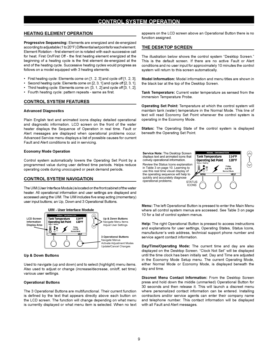
The UIM (User Interface Module) is located on the front cabinet of the water heater. All operational information and user settings are displayed and accessed using the UIM. The UIM includes five snap acting (momentary) user input buttons; an Up, Down and 3 Operational Buttons.
Up & Down Buttons
Used to navigate (up and down) and to select (highlight) menu items. Also used to adjust or change (increase/decrease, on/off, set time) various user settings.
Operational Buttons
The 3 Operational Buttons are multifunctional. Their current function is defined by the text that appears directly above each button on the LCD screen. The function will change depending on what menu is currently displayed or what menu item is selected. When no text
appears on the LCD screen above an Operational Button there is no function assigned.
THE DESKTOP SCREEN
The illustration below shows the control system “Desktop Screen.” This is the default screen. If there are no active Fault or Alert conditions and no user input for approximately 10 minutes the control system will return to this screen automatically.
Model Information: Model information and menu titles are shown in the black bar at the top of the Desktop Screen.
Tank Temperature: Current water temperature as sensed from the immersion Temperature Probe.
Operating Set Point: Temperature at which the control system will maintain tank (water) temperature in the Normal Mode. This line of text will read Economy Set Point whenever the control system is operating in the Economy Mode.
Status: The Operating State of the control system is displayed beneath the Operating Set Point.
Menu: The left Operational Button is pressed to enter the Main Menu where all control system menus are accessed. See Table 3 on page 10 for a list of control system menus.
Help: The right Operational Button is pressed to access instructions and explanations for user settings, Operating States, Status Icons, manufacturer’s web address, technical support phone number and service agent contact information.
Day/Time/Operating Mode: The current time and day are also displayed on the Desktop Screen. “Clock Not Set” will be displayed until the time clock has been initially set. Day and Time are adjusted in the Economy Mode Setup menu. The current Operating Mode, either Normal Mode or Economy Mode, is displayed beneath the day and time.
Discreet Menu Contact Information: From the Desktop Screen press and hold down the middle (unmarked) Operational Button for 30 seconds and then release it. This will launch a discreet menu where personalized contact information can be entered. Installing contractors and/or service agents can enter their company name and telephone number. This contact information will be displayed with all Fault and Alert messages.
9