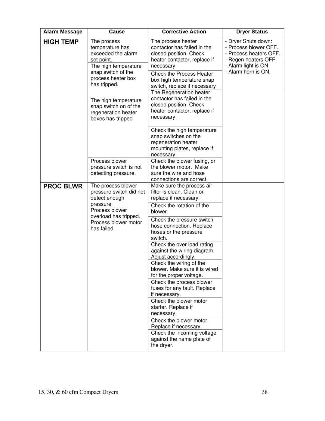
We are committed to a continuing program of product improvement
SDA Series 15, 30, & 60 cfm Compact Dehumidifying Dryers
Part Number Bulletin Number DH1-635.3 Effective
DCN No Copyright
In the Event of Shipping Damage
Shipping Information
Unpacking and Inspection
If the Shipment is Not Complete
CHAPTER 1 SAFETY
Table of Contents
CHAPTER 4 OPERATION
CHAPTER 3 INSTALLATION
CHAPTER 7 APPENDIX
CHAPTER 5 MAINTENANCE
CHAPTER 6 TROUBLESHOOTING
Safety Symbols Used in this Manual
Chapter 1 Safety
1-1 How to Use This Manual
Read Operation and Installation Manual Earth Ground
1-2 Safety Tag Information
1-3 Warnings and Precautions
Dryer Safety Tags
Operator Responsibility
1-4 Responsibility
General Responsibility
REMEMBER
Maintenance Responsibility
Reporting a Safety Defect
2-2 General Description
Chapter 2 Functional Description
2-1 Models Covered in This Manual
What is desiccant?
Mechanical Features
2-3 Standard Features
Figure 1 Typical Dryer Air Flow Schematic
Electrical Features
Controller Features
2-5 Safety Devices and Interlocks
2-4 Options
residual heat coming out of the desiccant tank prior to
Fail Safe Operation
Safety Circuit Standards
Safety Device Lock-Outs
3-2 Rigging and Placing the Dryer
Chapter 3 Installation
3-1 Uncrating the Equipment
Note Floor Mounted Dryers can be lifted by hoist or fork lift
Figure 2 Suggested Lift Rigging for Cart Mount Dryers
Figure 3 Suggested Lift Rigging for Floor Mounted Dryers
3-3 Electrical Connections
Figure 4 Suggested Lift Rigging for Machine Mounted Dryers
Making Dryer/Drying Hopper Process Air Connections Floor Mount Models
3-4 Setup Procedures
Checking for Proper Blower Rotation Three-Phase Models
Caution! Clean the rust-preventing oil from inside the drying hopper
3-5 Initial Start-up
Installing Water Lines
Drying Hopper Air Trap Considerations
Auto-Tuning the Dryer
Shutting Down the Dryer
Switches
Chapter 4 Operation
4-1 Controller Description and Operation
Indicator Lights
Process Air Temperature Controller
Figure 6 Typical Process Air Temperature Controller PV SV
Lit when Control Output 1 is on. The Out1
Identifying Process Air Temperature Controller LED Indicators
Indicator
Lit when Control Output 2 is on. Not used in
Adjustment Level
Setting the Process Air Temperature
Indicator
Indicator
The PV readout will display the different parameters within each mode
Process Air Dew Point Display
Setting the High Dew Point Alarm
Restoring the Process Air Dew Point Meter E5CK to Factory Setup
Optional
4-2 Dryer Operation Procedures
Controller Operation
Alarm Display Messages
Note A change will NOT take effect until step 12-c is done
Valve Motor Time-Out Blower Overload No Alarms
HIGH TEMP VALVE MTR
HEAT COOL 50 SYSTEM NORMAL
PROC BLWR
Every Day
Chapter 5 Maintenance
5-1 Preventative Maintenance Schedule
Every week
Figure 9 Air Filter Location and Disassembly
5-2 Preventative Maintenance
Recommendations for Cleaning and Replacing Filters
Servicing Process Air Filters
Caution! DO NOT clean/wash filter with water
5-3 Corrective Maintenance
Cleaning with Compressed Air
Symptoms of Worn Desiccant
WARNING! Handling desiccant material is HAZARDOUS
+ FIRST AID +
SEE A PHYSICIAN IMMEDIATELY IF IRRITATION PERSISTS
Handle with adequate ventilation Wash hands thoroughly after handling
Consult local disposal regulations for more information
Figure 10 Desiccant Bed Location and Disassembly
Caution! You should properly dispose of any discarded desiccant
Figure 11 Required Desiccant Amounts 13X Type
Procedures
Disconnect and lock out power before you replace heater elements
Figure 12 Process/Regeneration Heater Location and Disassembly
Replacing the Process/Regeneration Heater
Replacement Procedures
Replacing/Cleaning the Cooling Coil
Figure 13 Cooling Coil Location and Disassembly
If used as an after-Cooler 3 to 4 GPM @ 85F
15, 30, & 60 cfm Compact Dryers
8. Inset the four 10-32 bolts back in place
9. Turn the water to the cooling coil back on
HIGH TEMP
Chapter 6 Troubleshooting
6-1 Introduction
HIGH TEMP
PROC BLWR
Alarm Message
Cause
Using a Thermocouple
6-2 Determining Temperature Controller Errors or Sensor Errors
VALVE MTR
Alarm Message
Annex B Information
7-1 Technical Specifications
Chapter 7 Appendix
Figure 14 Standard Model 180F to 230F Air Flow Schematic
7-2 Drawings and Diagrams
Aftercooler Design Specifications
Regeneration MoistureMake Up Air Exhaust
After-Cooler Regeneration MoistureMake Up Air Exhaust
Figure 15 High Heat Model 180F to 400F Air Flow Schematic
Figure 16 Low Heat Model 120F to 250F Air Flow
High Pressure Peripheral Blower
DRYER SPARE PARTS LIST 15, 30, 60 cfm Models
7-3 Spare Parts List
Figure 18 Level 1 Spare Parts List Electrical & Mechanical
Mechanical Components
Description
HI-CORE DESICCANT DRYER 15/30/60 CFM UNITS
15 CFM
Description
15, 30, & 60 cfm Compact Dryers
30 CFM
Description
15, 30, & 60 cfm Compact Dryers
60 CFM
15, 30, & 60 cfm Compact Dryers
A0534047
15, 30, & 60 cfm Compact Dryers
Warranty Returns
7-5 Returned Material Policy
7-6 Dryer Identification Serial Number Tag
Credit Returns
Parts Department
7-7 Technical Assistance
Service Department
Sales Department