Chapter 4: Operation
4-1 Controller Description and Operation
Identifying Control Panel Indicator Lights and Switches for the Standard Controller
Switches
Main Power. This switch allows the dryer to receive power from the main power supply (3 phase only).
Dryer Control ON/OFF Switch. This switch energizes or
Indicator Lights
Alarm Light. This feature warns the operator of a high bed safety temperature, a regeneration heater fault, or a blower failure.
Power On. This light illuminates when the main power switch is on telling the user the dryer is energized.
Dryer Operating: Indicates the process air blower is on.
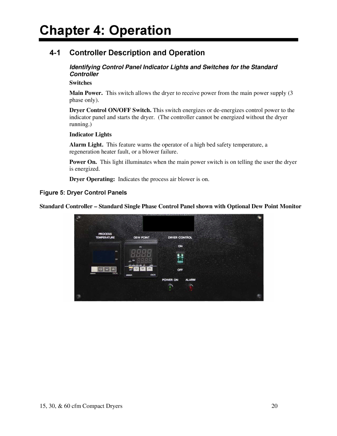
Figure 5: Dryer Control Panels
Standard Controller – Standard Single Phase Control Panel shown with Optional Dew Point Monitor
15, 30, & 60 cfm Compact Dryers | 20 |