7-5 Returned Material Policy
Credit Returns
Prior to the return of any material authorization must be given by the manufacturer. A RMA number will be assigned for the equipment to be returned.
Reason for requesting the return must be given.
ALL returned material purchased from the manufacturer returned is subject to 15% ($75.00 minimum) restocking charge.
ALL returns are to be shipped prepaid.
The invoice number and date or purchase order number and date must be supplied.
No credit will be issued for material that is not within the manufacturer’s warranty period and/or in new and unused condition, suitable for resale.
Warranty Returns
Prior to the return of any material, authorization must be given by the manufacturer. A RMA number will be assigned for the equipment to be returned.
Reason for requesting the return must be given. All returns are to be shipped prepaid.
The invoice number and date or purchase order number and date must be supplied.
After inspecting the material, a replacement or credit will be given, at the manufacturer’s discretion. If the item is found to be defective in materials or workmanship, and it was manufactured by our company, purchased components are covered under their specific warranty terms.
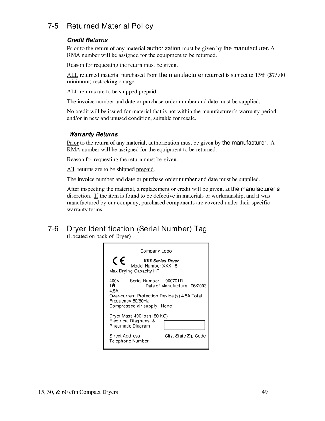
7-6 Dryer Identification (Serial Number) Tag
(Located on back of Dryer)
| Company Logo | |||
| XXX Series Dryer | |||
| Model Number | |||
Max Drying Capacity HR |
|
|
| |
460V | Serial Number |
| 060701R | |
1Ǿ | Date of Manufacture 06/2003 | |||
4.5A |
|
|
|
|
Frequency 50/60Hz |
|
|
| |
Compressed air supply | None | |||
Dryer Mass 400 lbs/(180 KG) | ||||
Electrical Diagrams & |
|
|
| |
|
|
| ||
Pneumatic Diagram |
|
|
| |
|
|
|
| |
Street Address |
| City, State Zip Code | ||
Telephone Number |
|
|
| |
|
|
|
|
|
15, 30, & 60 cfm Compact Dryers | 49 |