12V (e.g. due to a high load on the batteries), the entire charging cycle will be repeated.
Troubleshooting
Unit is not working at all (no LEDs)
After you have started the engine, check the voltage at the main alternator input of the unit. You should be able to measure at least 13V. If you do not measure any voltage at all, it is possible that your alternator requires a voltage on the output to fire up. (See Extended Installation.) In this case connect an extra wire from the terminal named “STARTER SOLENOID” to the positive terminal of the starter solenoid.
If the input voltage on the unit is 13V or above and you still can’t see any LEDs lighting up, check the internal fuse (7) of the unit and replace if necessary. If the new fuse blows again, please contact the Sterling customer service.
Unit is not boosting the voltage
Most regulators come set with a standard output between about 13.8V and 14.4V. If the standard regulator does not work within these limits and has an output voltage below 13.8V, then the unit may not boost. In this case set the regulation voltage switch (14) to the “ON” position. This will drop the engine battery charge from appr. 13V to appr. 12.8V which in turn improves the boost effect on the domestic battery side.
Warning: Do not do this unless you have the
Appendix 1: LED Information and Alarms
LED 1 - CONSTANT CURRENT (green)
A constant green LED (with LED 2 off) indicates that the unit is in the bulk charge phase.
A flashing green LED indicates that the unit is in pause mode to provide additional charge capacity for the starter battery.
LED 2 - TIME CONTROL ON (yellow)
This LED indicates that the voltage is approaching or has reached the absorption level. It will come on only in addition to LED 1.
LED 3 - FLOAT/POWERPACK (green)
This LED indicates that the absorption charge has been finished and that the batteries have been fully charged. It remains on until the unit is switched off or until the next charge cycle starts.
LED 4 - LOW BATTERY V (orange)
This LED will come on when the domestic battery voltage as sensed by the unit, is below 13V. Often this indicates a defective alternator or battery.
LED 5 - HIGH BAT V/ TEMP (FL) (red)
A constant red LED means that the unit has tripped because of high voltage at the domestic battery. Often, this indicates a failure of the alternator regulator or another charging unit.
A flashing red LED means that the domestic battery temperature, as sensed by the unit, is above 50°C and that the charge cycle has been suspended. Often, this indicates a defective battery.
LED 6 - BATTERY TYPE (yellow, green, red)
This LED displays the battery type that the unit has been set up for. It will be
!yellow, for open
!green, for gel batteries (Exide specification)
!flashing green, then off, for gel batteries (U.S. specification), and
!red, for sealed
LED 7 - HIGH ALT VOLTS (red)
This LED indicates that the unit has tripped because of high
voltage (> 15.5V) on the alternator. It usually means that the alternator’s own regulator has failed. Check the voltage and, if necessary, stop your engine as soon as possible and disconnect the alternator input cable, or you will boil and destroy your batteries!
LED 8 - HIGH ALT TEMP, STOP (yellow)
This LED will come on when the alternator temperature as sensed by the unit, is above 90°C. The charge cycle will be suspended until the alternator has cooled down to 75°C or below.
A flashing yellow LED means that the
LED 9 - UNIT FAILURE RHS (red)
This LED warns you that the unit’s integrated split charge diode has failed on the right hand side. Restart the unit. If the fault persists, please contact the Sterling customer service.
LED 10 - UNIT FAILURE LHS (red)
This LED warns you that the unit’s integrated split charge diode has failed on the left hand side. Restart the unit. If the fault persists, please contact the Sterling customer service.
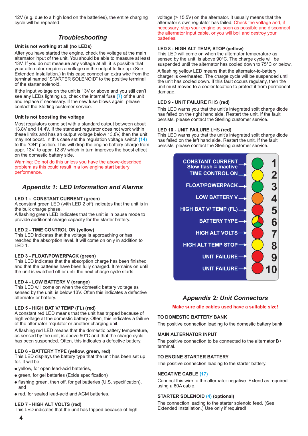
CONSTANT CURRENT | 1 |
Slow flash = inactive |
TIME CONTROL ON | 2 | |
| ||
FLOAT/POWERPACK | 3 | |
| ||
LOW BATTERY V | 4 | |
| ||
HIGH BAT V/ TEMP (FL) | 5 | |
| ||
BATTERY TYPE | 6 | |
HIGH ALT VOLTS | 7 | |
8 | ||
HIGH ALT TEMP STOP | ||
9 | ||
UNIT FAILURE | ||
10 | ||
UNIT FAILURE | ||
|
Appendix 2: Unit Connectors
Make sure alle cables used have a suitable size!
TO DOMESTIC BATTERY BANK
The positive connection leading to the domestic battery bank.
MAIN ALTERNATOR INPUT
The positive connection to be connected to the alternator B+ terminal.
TO ENGINE STARTER BATTERY
The positive connection leading to the starter battery.
NEGATIVE CABLE (17)
Connect this wire to the alternator negative. Extend as required using a 60A cable.
STARTER SOLENOID (4) (optional)
The connection leading to the starter solenoid feed. (See Extended Installation.) Use only if required!
4