REMOTE DOM SENSE (3) (optional)
The connection leading to the positive terminal of the domestic battery. (See Extended Installation.) Installation is optional.
ALTERNATOR TEMP SENSOR (2) (optional)
Connection for the alternator temperature sensor. Installation is optional.
BATTERY TEMP SENSOR (1) (optional)
Connection for the battery temperature sensor. Installation is optional.
REMOTE CONTROL (5) (optional)
Connection for the optional remote control.
ALTERNATOR INPUT SHUNT (optional)
Connection for the alternator input shunt which is part of the remote control package.
STARTER BATTERY SHUNT (optional)
Connection for the starter battery shunt which is part of the remote control package.
UNIT EXPECTATIONS
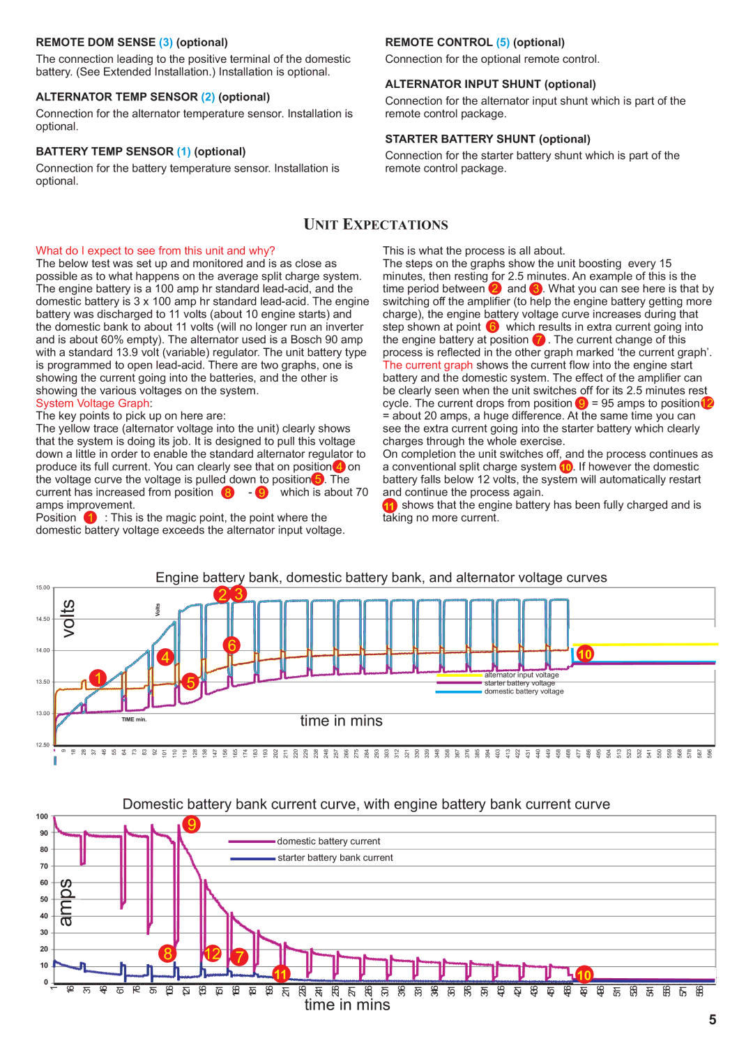
What do I expect to see from this unit and why?
The below test was set up and monitored and is as close as possible as to what happens on the average split charge system. The engine battery is a 100 amp hr standard
System Voltage Graph:
The key points to pick up on here are:
The yellow trace (alternator voltage into the unit) clearly shows that the system is doing its job. It is designed to pull this voltage down a little in order to enable the standard alternator regulator to produce its full current. You can clearly see that on position 4 on the voltage curve the voltage is pulled down to position 5 . The current has increased from position 8 - 9 which is about 70 amps improvement.
Position 1 : This is the magic point, the point where the domestic battery voltage exceeds the alternator input voltage.
This is what the process is all about.
The steps on the graphs show the unit boosting every 15 minutes, then resting for 2.5 minutes. An example of this is the time period between 2 and 3 . What you can see here is that by switching off the amplifier (to help the engine battery getting more charge), the engine battery voltage curve increases during that step shown at point 6 which results in extra current going into the engine battery at position 7 . The current change of this process is reflected in the other graph marked ‘the current graph’. The current graph shows the current flow into the engine start battery and the domestic system. The effect of the amplifier can be clearly seen when the unit switches off for its 2.5 minutes rest cycle. The current drops from position 9 = 95 amps to position12
=about 20 amps, a huge difference. At the same time you can see the extra current going into the starter battery which clearly charges through the whole exercise.
On completion the unit switches off, and the process continues as a conventional split charge system 10 . If however the domestic battery falls below 12 volts, the system will automatically restart and continue the process again.
11 shows that the engine battery has been fully charged and is taking no more current.
Engine battery bank, domestic battery bank, and alternator voltage curves
15.00 |
|
|
|
|
|
|
|
|
|
|
|
|
|
|
|
| 2 3 |
|
|
|
|
|
|
|
|
|
|
|
|
|
|
|
|
|
|
|
|
|
|
|
|
|
|
|
|
|
|
|
|
|
|
|
|
|
|
|
|
|
|
|
|
|
|
| |
| volts |
|
|
|
|
|
|
| Volts |
|
|
|
|
|
|
|
|
|
|
|
|
|
|
|
|
|
|
|
|
|
|
|
|
|
|
|
|
|
|
|
|
|
|
|
|
|
|
|
|
|
|
|
|
|
|
|
|
|
|
|
|
| |||
14.50 |
|
|
|
|
|
|
|
|
|
|
|
|
|
|
|
|
|
|
|
|
|
|
|
|
|
|
|
|
|
|
|
|
|
|
|
|
|
|
|
|
|
|
|
|
|
|
|
|
|
|
|
|
|
|
|
|
|
|
|
|
|
| |||
|
|
|
|
|
|
|
|
|
|
|
|
|
|
| 6 |
|
|
|
|
|
|
|
|
|
|
|
|
|
|
|
|
|
|
|
|
|
|
|
|
|
|
|
|
|
|
|
|
| 10 |
|
|
|
|
|
|
|
|
|
|
|
| ||||
14.00 |
|
|
|
|
|
|
|
|
|
| 4 |
|
|
|
|
|
|
|
|
|
|
|
|
|
|
|
|
|
|
|
|
|
|
|
|
|
|
|
|
|
|
|
|
|
|
|
|
|
|
|
|
|
|
|
|
|
|
|
|
|
|
| |||
|
|
|
|
|
|
|
|
|
|
|
|
|
|
|
|
|
|
|
|
|
|
|
|
|
|
|
|
|
|
|
|
|
|
|
|
|
|
|
|
|
|
|
|
|
|
|
|
|
|
|
|
|
|
|
|
|
|
|
|
|
|
| |||
|
|
|
| 1 |
|
|
|
|
|
|
|
|
| 5 |
|
|
|
|
|
|
|
|
|
|
|
|
|
|
|
|
|
|
|
|
|
|
|
|
|
|
|
| alternator input voltage |
|
|
|
|
|
|
|
|
|
|
|
|
|
|
| |||||||
13.50 |
|
|
|
|
|
|
|
|
|
|
|
|
|
|
|
|
|
|
|
|
|
|
|
|
|
|
|
|
|
|
|
|
|
|
|
|
|
|
|
| starter battery voltage |
|
|
|
|
|
|
|
|
|
|
|
|
|
|
|
| ||||||||
|
|
|
|
|
|
|
|
|
|
|
|
|
|
|
|
|
|
|
|
|
|
|
|
|
|
|
|
|
|
|
|
|
|
|
|
|
|
|
|
|
|
| domestic battery voltage |
|
|
|
|
|
|
|
|
|
|
|
|
|
|
| |||||||
13.00 |
|
|
|
|
|
| TIME min. |
|
|
|
|
|
|
|
|
|
|
|
|
|
|
| time in mins |
|
|
|
|
|
|
|
|
|
|
|
|
|
|
|
|
|
|
|
|
|
|
|
|
|
|
|
|
|
|
|
|
| |||||||||
|
|
|
|
|
|
|
|
|
|
|
|
|
|
|
|
|
|
|
|
|
|
|
|
|
|
|
|
|
|
|
|
|
|
|
|
|
|
|
|
|
|
|
|
|
|
|
|
|
|
|
|
|
|
| |||||||||||
|
|
|
|
|
|
|
|
|
|
|
|
|
|
|
|
|
|
|
|
|
|
|
|
|
|
|
|
|
|
|
|
|
|
|
|
|
|
|
|
|
|
|
|
|
|
|
|
|
|
|
|
|
|
|
|
|
| ||||||||
12.50 | 9 | 18 | 28 | 37 | 46 | 55 | 64 | 73 | 83 | 92 | 101 | 110 | 119 | 128 | 138 | 147 | 156 | 165 | 174 | 183 | 193 | 202 | 211 | 220 | 229 | 238 | 248 | 257 | 266 | 275 | 284 | 293 | 303 | 312 | 321 | 330 | 339 | 348 | 358 | 367 | 376 | 385 | 394 | 403 | 413 | 422 | 431 | 440 | 449 | 458 | 468 | 477 | 486 | 495 | 504 | 513 | 523 | 532 | 541 | 550 | 559 | 568 | 578 | 587 | 596 |
| |||||||||||||||||||||||||||||||||||||||||||||||||||||||||||||||||
Domestic battery bank current curve, with engine battery bank current curve
100 |
|
|
|
|
|
|
| 9 |
|
|
|
|
|
|
|
|
|
|
|
|
|
|
|
|
|
|
|
|
|
|
|
|
|
|
|
|
|
|
|
90 |
|
|
|
|
|
|
|
|
|
|
|
| domestic battery current |
|
|
|
|
|
|
|
|
|
|
|
|
|
|
|
|
|
|
|
| ||||||
|
|
|
|
|
|
|
|
|
|
|
|
|
|
|
|
|
|
|
|
|
|
|
|
|
|
|
|
|
|
|
|
| |||||||
80 |
|
|
|
|
|
|
|
|
|
|
|
|
|
|
|
|
|
|
|
|
|
|
|
|
|
|
|
|
|
|
|
|
| ||||||
|
|
|
|
|
|
|
|
|
|
|
|
| starter battery bank current |
|
|
|
|
|
|
|
|
|
|
|
|
|
|
|
|
|
|
| |||||||
70 |
|
|
|
|
|
|
|
|
|
|
|
|
|
|
|
|
|
|
|
|
|
|
|
|
|
|
|
|
|
|
|
| |||||||
|
|
|
|
|
|
|
|
|
|
|
|
|
|
|
|
|
|
|
|
|
|
|
|
|
|
|
|
|
|
|
|
|
|
|
|
|
|
| |
60 | ampsAmps |
|
|
|
|
|
|
|
|
|
|
|
|
|
|
|
|
|
|
|
|
|
|
|
|
|
|
|
|
|
|
|
|
|
|
|
|
|
|
50 |
|
|
|
|
|
|
|
|
|
|
|
|
|
|
|
|
|
|
|
|
|
|
|
|
|
|
|
|
|
|
|
|
|
|
|
|
|
| |
40 |
|
|
|
|
|
|
|
|
|
|
|
|
|
|
|
|
|
|
|
|
|
|
|
|
|
|
|
|
|
|
|
|
|
|
|
|
|
| |
30 |
|
|
|
|
|
|
|
|
|
|
|
|
|
|
|
|
|
|
|
|
|
|
|
|
|
|
|
|
|
|
|
|
|
|
|
|
|
| |
|
|
|
|
|
|
|
|
|
|
|
|
|
|
|
|
|
|
|
|
|
|
|
|
|
|
|
|
|
|
|
|
|
|
|
|
|
|
| |
20 |
|
|
|
|
|
| 8 |
| 12 | 7 |
|
|
|
|
|
|
|
|
|
|
|
|
|
|
|
|
|
|
|
|
|
|
|
|
|
|
|
| |
10 |
|
|
|
|
|
|
|
|
| 11 |
|
|
|
|
|
|
|
|
|
|
|
|
|
|
|
|
| 10 |
|
|
|
|
|
|
| ||||
|
|
|
|
|
|
|
|
|
|
|
|
|
|
|
|
|
|
|
|
|
|
|
|
|
|
|
|
|
|
|
|
|
|
|
|
| |||
0 | T im e | m i n . |
|
|
|
|
|
|
|
|
|
|
|
|
|
|
|
|
|
|
|
|
|
|
|
|
|
|
|
|
|
|
|
|
|
| |||
|
|
|
|
|
| 106 | 121 | 136 | 151 | 166 | 181 | 196 | 211 | 226 | 241 | 256 | 271 | 286 | 301 | 316 | 331 | 346 | 361 | 376 | 391 | 406 | 421 | 436 | 451 | 466 | 481 | 496 | 511 | 526 | 541 | 556 | 571 | 586 | |
1 | 16 | 31 | 46 | 61 | 76 | 91 | |||||||||||||||||||||||||||||||||
time in mins
5