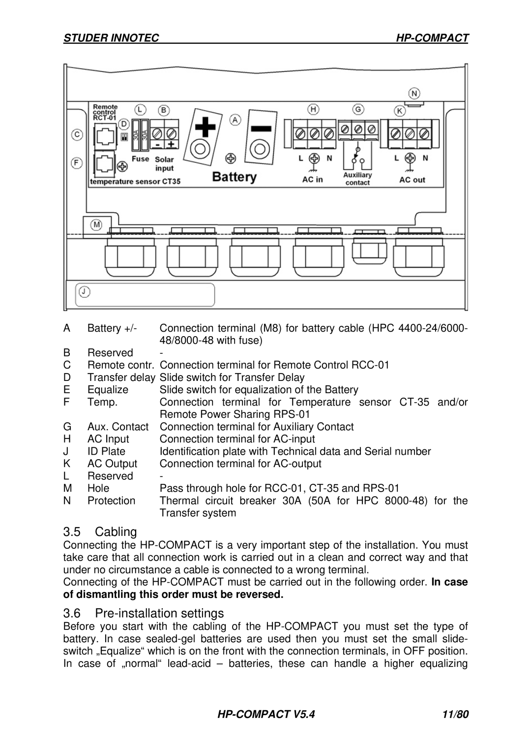
Studer Innotec HPC 2800-12, HPC 4400-24, HPC 6000-48, HPC 8000-48 manual Cabling

Models: HPC 2800-12, HPC 4400-24, HPC 6000-48, HPC 8000-48

1 26
Download 26 pages 16.28 Kb
Page 9
Image 9

STUDER INNOTEC

HP-COMPACT

A

Battery +/-

Connection terminal (M8) for battery cable (HPC 4400-24/6000-


48/8000-48 with fuse)

B

Reserved

-

CRemote contr. Connection terminal for Remote Control RCC-01

DTransfer delay Slide switch for Transfer Delay

E

Equalize

Slide switch for equalization of the Battery

F

Temp.

Connection terminal for Temperature sensor CT-35 and/or


Remote Power Sharing RPS-01

G

Aux. Contact

Connection terminal for Auxiliary Contact

H

AC Input

Connection terminal for AC-input

J

ID Plate

Identification plate with Technical data and Serial number

K

AC Output

Connection terminal for AC-output

L

Reserved

-

M

Hole

Pass through hole for RCC-01, CT-35 and RPS-01

N

Protection

Thermal circuit breaker 30A (50A for HPC 8000-48) for the


Transfer system

3.5Cabling

Connecting the HP-COMPACT is a very important step of the installation. You must take care that all connection work is carried out in a clean and correct way and that under no circumstance a cable is connected to a wrong terminal.

Connecting of the HP-COMPACT must be carried out in the following order. In case

of dismantling this order must be reversed.

3.6Pre-installation settings

Before you start with the cabling of the HP-COMPACT you must set the type of battery. In case sealed-gel batteries are used then you must set the small slide- switch „Equalize“ which is on the front with the connection terminals, in OFF position. In case of „normal“ lead-acid – batteries, these can handle a higher equalizing

HP-COMPACT V5.4

11/80

Page 9
Image 9
Studer Innotec HPC 2800-12, HPC 4400-24, HPC 6000-48, HPC 8000-48 manual Cabling, Pre-installation settings