STUDER INNOTEC |
|
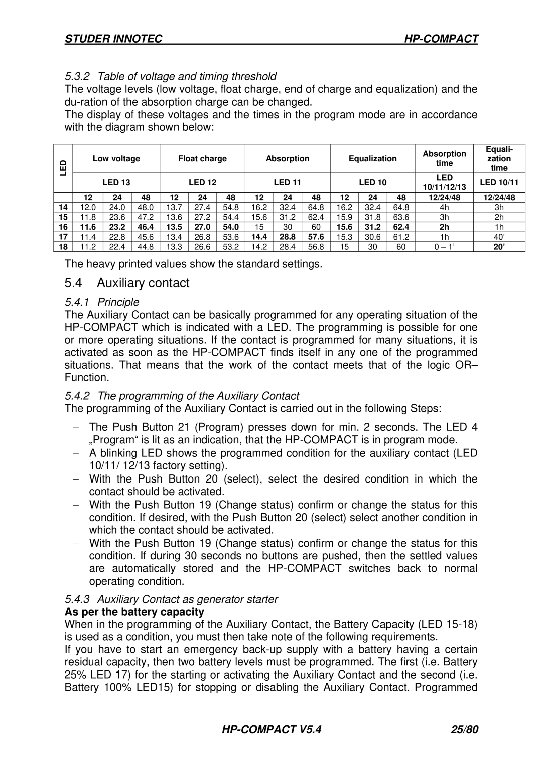
5.3.2 Table of voltage and timing threshold
The voltage levels (low voltage, float charge, end of charge and equalization) and the
The display of these voltages and the times in the program mode are in accordance with the diagram shown below:
|
|
|
|
|
|
|
|
|
|
|
|
|
| Absorption | Equali- | |
LED | Low voltage | Float charge | Absorption | Equalization | zation | |||||||||||
time | ||||||||||||||||
|
|
|
|
|
|
|
|
|
|
|
|
| time | |||
|
|
|
|
|
|
|
|
|
|
|
|
|
| |||
|
|
|
|
|
|
|
|
|
|
|
|
|
|
| ||
|
| LED 13 |
|
| LED 12 |
|
| LED 11 |
|
| LED 10 |
| LED | LED 10/11 | ||
|
|
|
|
|
|
|
|
| 10/11/12/13 | |||||||
|
|
|
|
|
|
|
|
|
|
|
|
|
|
| ||
| 12 |
| 24 | 48 | 12 | 24 | 48 | 12 | 24 | 48 | 12 | 24 | 48 | 12/24/48 | 12/24/48 | |
14 | 12.0 |
| 24.0 | 48.0 | 13.7 | 27.4 | 54.8 | 16.2 | 32.4 | 64.8 | 16.2 | 32.4 | 64.8 | 4h | 3h | |
15 | 11.8 |
| 23.6 | 47.2 | 13.6 | 27.2 | 54.4 | 15.6 | 31.2 | 62.4 | 15.9 | 31.8 | 63.6 | 3h | 2h | |
16 | 11.6 |
| 23.2 | 46.4 | 13.5 | 27.0 | 54.0 | 15 | 30 | 60 | 15.6 | 31.2 | 62.4 | 2h | 1h | |
17 | 11.4 |
| 22.8 | 45.6 | 13.4 | 26.8 | 53.6 | 14.4 | 28.8 | 57.6 | 15.3 | 30.6 | 61.2 | 1h | 40’ | |
18 | 11.2 |
| 22.4 | 44.8 | 13.3 | 26.6 | 53.2 | 14.2 | 28.4 | 56.8 | 15 | 30 | 60 | 0 – 1’ | 20’ | |
The heavy printed values show the standard settings.
5.4Auxiliary contact
5.4.1 Principle
The Auxiliary Contact can be basically programmed for any operating situation of the
5.4.2 The programming of the Auxiliary Contact
The programming of the Auxiliary Contact is carried out in the following Steps:
−The Push Button 21 (Program) presses down for min. 2 seconds. The LED 4 „Program“ is lit as an indication, that the
−A blinking LED shows the programmed condition for the auxiliary contact (LED 10/11/ 12/13 factory setting).
−With the Push Button 20 (select), select the desired condition in which the contact should be activated.
−With the Push Button 19 (Change status) confirm or change the status for this condition. If desired, with the Push Button 20 (select) select another condition in which the contact should be activated.
−With the Push Button 19 (Change status) confirm or change the status for this condition. If during 30 seconds no buttons are pushed, then the settled values are automatically stored and the
5.4.3Auxiliary Contact as generator starter
As per the battery capacity
When in the programming of the Auxiliary Contact, the Battery Capacity (LED
If you have to start an emergency
Battery 100% LED15) for stopping or disabling the Auxiliary Contact. Programmed
| 25/80 |