UNINETIMAGINGHP P4014,INCINC. . •P4015• BROTHER& P40451240/1650CARTRIDGE REMANUFACTURING• • DISASSEMBLINGINSTRUCTIONSTHETHETONERCARTRIDGE
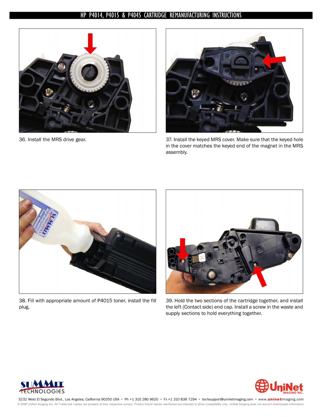
36. Install the MRS drive gear.
38.Fill with appropriate amount of P4015 toner, install the fill plug.
37.Install the keyed MRS cover. Make sure that the keyed hole in the cover matches the keyed end of the magnet in the MRS assembly.
39.Hold the two sections of the cartridge together, and install the left (Contact side) end cap. Install a screw in the waste and supply sections to hold everything together.
SUMMIT
3232 West El Segundo Blvd., Los Angeles, California 90250 USA • Ph +1 310 280 9620 • Fx +1 310 838 7294 • techsupport@uninetimaging.com • www.uninetimaging.com
© 2008 UniNet Imaging Inc. All Trademark names are property of their respective owners. Product brand names mentioned are intended to show compatibility only. UniNet Imaging does not warrant downloaded information.