Appendix A: SC512 Chassis Cables
A-3 Routing the Chassis Cables
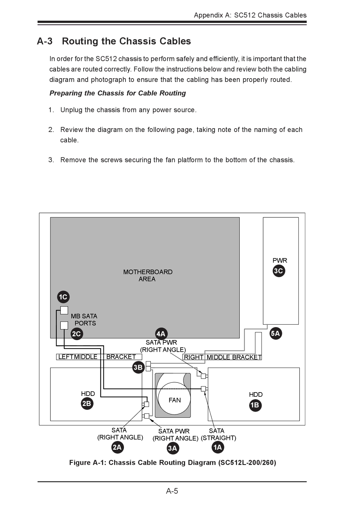
In order for the SC512 chassis to perform safely and efficiently, it is important that the cables are routed correctly. Follow the instructions below and review both the cabling diagram and photograph to ensure that the cabling has been properly routed.
Preparing the Chassis for Cable Routing
1.Unplug the chassis from any power source.
2.Review the diagram on the following page, taking note of the naming of each cable.
3.Remove the screws securing the fan platform to the bottom of the chassis.
|
|
| PWR |
| MOTHERBOARD | 3C | |
| AREA | 1 | |
|
| ||
1C |
|
|
|
1 |
|
|
|
MB SATA |
|
|
|
PORTS |
|
|
|
2C |
| 4A | 5A |
1 |
| 1 | 1 |
|
| SATA PWR |
|
LEFTMIDDLE | (RIGHT ANGLE) |
| |
BRACKET | RIGHT MIDDLE BRACKET | ||
| 3B |
|
|
| 1 |
|
|
HDD |
| FAN | HDD |
2B |
| 1B | |
1 |
|
| |
|
|
| 1 |
| SATA | SATA PWR | SATA |
(RIGHT ANGLE) | (RIGHT ANGLE) (STRAIGHT) | ||
| 2A1 | 3A1 | 1A1 |
Figure | |||