Manuals
/
SUPER MICRO Computer
/
Computer Equipment
/
Computer Hardware
SUPER MICRO Computer
X8ST3-F, X8STE
user manual
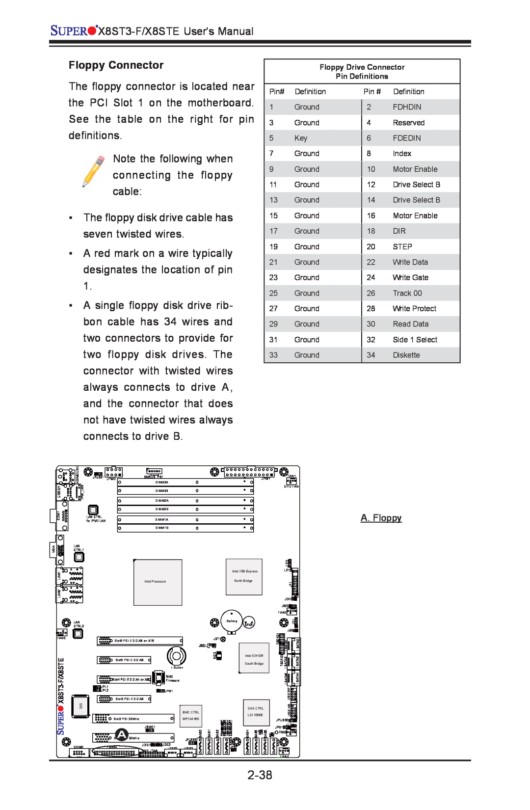
2-38, Floppy Connector, A. Floppy
Models:
X8STE
X8ST3-F
1
62
103
103
Download
103 pages
24.8 Kb
59
60
61
62
63
64
65
66
Troubleshooting
Install
FAQ
Alarm Reset
Password
Memory Errors
High Performance Event Timer
X8ST3-F/X8STE LED Indicators
Connecting Cables
Dimension
Page 62
Image 62
Page 61
Page 63
Page 62
Image 62
Page 61
Page 63
Contents
USER’S MANUAL
Revision 1.0b
X8ST3-F X8STE
Printed in the United States of America
Manual Organization
Preface
About This Motherboard
Conventions Used in the Manual
Europe
Contacting Supermicro
Headquarters
Asia-Pacific
Preface
Table of Contents
Chapter 2 Installation
Chapter 1 Introduction
Table of Contents
Appendix A POST Error Beep Codes
Chapter 3 Troubleshooting
Chapter 4 BIOS
Appendix B Installing the Windows OS
1-1 Overview
Checklist
Chapter Introduction
X8ST3-F Image
Important Notes to the User
Motherboard Layout
X8ST3-F/X8STE Jumpers
Default Setting
X8ST3-F/X8STE Quick Reference
Jumper
Connector
X8ST3-F/X8STE LED Indicators
X8ST3-F/X8STE Headers/Connectors
X8ST3-F/X8STE Jumpers
Chipset
Motherboard Features
Memory
Expansion Slots
Floppy Drive
BIOS
Power Configuration
SAS Connections for the X8ST3-F only
System Management
Dimensions
PC Health Monitoring
CD Utilities
Chapter 1 Introduction
RJ45
X8ST3-F/X8STE System Block Diagram
1-10
1-2 Chipset Overview
1-11
Slow Blinking LED for Suspend-State Indicator
1-4 Power Configuration Settings
Recovery from AC Power Loss
1-3 PC Health Monitoring
Main Switch Override Mechanism
1-5 Power Supply
BIOS Support for USB Keyboard
Wake-On-LAN WOL
1-14
1-6 Super I/O
1-7 Overview of the Winbond WPCM450 Controller
One X-Bus parallel interface for expansion I/O connections
1-15
The WPCM450 also includes the following features
Three ADC inputs, Analog and Digital Video outputs
1-16
2-1 Static-Sensitive Devices
Chapter Installation
Precautions
Unpacking
Socket Clip
2-2 Processor and Heatsink Installation
Installing an LGA 1366 Processor
Plastic Cap
Align CPU keys with socket keys
CPU CPU Socket
Load Plate
Heatsink Bracket BKT-0023L, for screw-type heatsink only
Installing a Passive CPU Heatsink #SNK-P0037
Install the Heatsink Bracket on the reverse side of the board
Passive Heatsink Removal
Tools Needed
Installation Instructions
2-3 Mounting the Motherboard into the Chassis
Installing and Removing DDR3 Memory
2-4 Installing and Removing the Memory Modules
Installing & Removing DIMMs
Front View
DIMM Module Population Configuration
Memory Support
Maximum Memory Possible
Possible System Memory Allocation & Availability
Back Panel Connectors
2-5 Connectors/IO Ports
Back Panel Connectors and IO Ports
2-10
Mouse
2-11
ATX PS/2 Keyboard and PS/2 Mouse Ports
Keyboard
Back Panel USB 0/1 Pin Definitions
2-12
Universal Serial Bus USB
Front Panel USB 2, 3, 4/5, 6/7
NC No Connection
2-13
Ethernet Ports
1. LAN1 2. LAN2 3 . I P M I D e d i c a t e d L A N X8ST3-F only
1. COM1 2. COM2
2-14
Serial Ports
1. VGA
Video Connector
2-15
2-16
JF1 Header Pins
Front Control Panel
2-17
Power LED
Front Control Panel Pin Definitions
NMI Button
HDD LED
NIC1/NIC2 LED Indicators
2-18
Overheat OH/Fan Fail LED
Power Fail LED
2-19
A. OH/Fan Fail LED B. PWR Supply Fail
2-20
Reset Button
Power Button
A. Reset Button B. PWR Button
2-21
2-6 Connecting Cables
ATX Main PWR & CPU PWR Connectors
Required A. 24-Pin ATX Main PWR B. 8-Pin Processor PWR
E. Fan5
2-22
Fan Headers
Speaker
2-23
Internal Buzzer
A. Internal Buzzer B. Speaker
Chassis Intrusion
2-24
Overheat/Fan Fail LED
A. Overheat/Fan Fail LED B. Chassis Intrusion
2-25
Power Supply I2C Connector
Onboard Power LED
A. PWR SMB B. PWR LED
T-SGPIO 0/1 & 3-SGPIO 0/1 Headers
Alarm Reset
2-26
D. 3-SPGIO 1 X8ST3-F only E. Alarm Reset
I-Button
2-27
Wake-On-LAN
A. WOL B. I-Button
Explanation of Jumpers
2-7 Jumper Settings
LAN Port Enable/Disable
2-28
CMOS Clear
Watch Dog Enable/Disable
2-29
A. Clear CMOS B. Watch Dog Enable
SMB to PCI-X/PCI-E Slots Speeds
BMC VGA Enable
2-30
C. VGA Enable
A. BP USB 0/1 Wake-up B. FP USB 4/5, 6/7 Wake-up
2-31
USB Wake-Up
C. FP USB 2, 3 Wake-up
SAS RAID Mode Select X8ST3-F Only
SAS Enable/Disable X8ST3-F Only
2-32
A. RAID Enable B. SAS RAID Mode Se- lect
A. BMC Enable
BMC IPMI Enable X7ST3-F only
2-33
LAN 1/LAN 2 LEDs
2-8 Onboard Indicators
IPMI LAN
IPMI Dedicated LAN LEDs X8ST3-F Only
SAS Heartbeat LED X8ST3-F Only
2-35
SAS Activity LED X8ST3-F Only
A. SAS Heartbeat B. SAS Activity
A. Onboard PWR LED
2-36
Onboard PWR LED Indicator LED Settings
2-37
SATA Connectors
2-9 Serial ATA and Floppy Drive Connections
A. I-SATA 0~1
A. Floppy
Floppy Connector
2-38
Before Power On
Chapter Troubleshooting
3-1 Troubleshooting Procedures
No Power
Losing the System’s Setup Configuration
3-2 Technical Support Procedures
Memory Errors
Question What type of memory does my motherboard support?
3-3 Frequently Asked Questions
Question How do I update my BIOS?
com/support/bios
3-4 Returning Merchandise for Service
Question Whats on the CD that came with my motherboard?
How To Change the Configuration Data
Chapter BIOS
Starting BIOS Setup Utility
4-1 Introduction
System Time/System Date
4-2 Main Setup
Starting the Setup Utility
AMIBIOS Version Build Date
Processor
System Memory
Physical Count Logical Count
Quick Boot
4-3 Advanced Setup Configurations
BOOT Feature
Quiet Boot
Processor & Clock Options
Wait For F1 If Error
Restore on AC Power Loss
Hit Del Message Display
Intel Virtualization Technology Available when supported by the CPU
Hardware Prefetcher Available when supported by the CPU
Adjacent Cache Line Prefetch Available when supported by the CPU
Simultaneous Multi-Threading Available when supported by the CPU
Intel EIST Technology
Intel TurboMode Tech Available if Intel EIST technology is Enabled
Intel Turbo Boost Configuration Turbo Ratio Limit Program
1 - Core Ratio Limit
C1E Support
C-State package limit setting
Intel C-STATE Architecture
C-STATE Tech
DCA Prefetch Delay
QPI and IMC Configuration
Advanced Chipset Control
QPI Links Speed
Patrol Scrubbing
4-10
Demand Scrubbing
Throttling - Open Loop
Air Flow
High Performance Event Timer
4-11
Altitude
USB Functions
Active State Power Management
4-12
USB 2.0 Controller
Configure SATA#1 as
IDE / Floppy Configuration
SATA#1 Configuration
SATA#2 Configuration
LBA/Large Mode
4-14
Type
Block Multi-Sector Transfer
S.M.A.R.T. For Hard disk drives
4-15
DMA Mode
Enabled Load Onboard LAN1 Option ROM, Load Onboard LAN2 Option ROM
PCI/PnP Configuration
PCI Latency Timer
4-16
Remote Access
Super IO Device Configuration
Remote Access Configuration
4-17
CPU Overheat Alarm
Hardware Health Configuration
Redirection After BIOS POST
4-18
4-19
CPU Temperature
4-20
ACPI Configuration
Disabled PS/2 KB/MS Wake-Up
Fan Speed Control Modes
Set LAN Configuration
IPMI Configuration X8ST3-F Only
ACPI Version Features
4-21
Set PEF Configuration
4-22
BMC WatchDog TimeOut MinSec
Event Log Configuration
BMC Watch Dog Timer Action
4-23
User Password
4-4 Security Settings
Supervisor Password
Change Supervisor Password
Boot Sector Virus Protection
4-5 Boot Configuration
Boot Device Priority
4-25
CD/DVD Drives
4-6 Exit Options
Removable Drives
4-26
4-27
Load Optimal Defaults
Load Fail-Safe Defaults
Discard Changes and Exit
4-28
Appendix A POST Error Beep Codes
Recoverable POST Error Beep Codes
Page
Appendix B Installing the Windows OS
B-1 Installing the Windows OS for Systems with RAID Functions
B-2 Installing the Windows OS for Systems without RAID Functions
Driver/Tool Installation Display Screen
Appendix C Software Installation Instructions
C-1 Installing Drivers
C-2 Configuring Supero Doctor
Supero Doctor III Interface Display Screen-I Health Information
Supero Doctor III Interface Display Screen-II Remote Control
X8ST3-F/X8STE Users Manual
Disclaimer continued
Top
Page
Image
Contents