Ne pas se servir de cet appareil s'il a été plongé dans l'eau, complètement ou en partie. Appeler un technicien qualifié pour inspecter l'appareil et remplacer toute partie du système de contrôle et toute commande qui ont été plongés dans l'leau.
Test gage connections are provided on the front of the millivolt gas control valve (identi- fied OUT for the manifold side and IN for inlet pressure. A ¹⁄₈" NPT test gage connection is provided on the electronic gas control valve adjacent to the outlet to the main burner.
Minimum inlet gas pressure to these appliances is 5.0 inches water column (1.24 kPa) for natural gas and 11 inches water column (2.74 kPa) for propane for the purpose of input adjustment.
Maximum inlet gas supply pressure to these appliances is 10.5 inches water column (2.61 kPa) for natural gas and 13.0 inches water column (3.23 kPa) for propane.
The appliance must be isolated from the gas supply piping system (by closing its individual manual
The appliance and its individual
These appliances must not be connected to a chimney or flue serving a separate solid fuel burning appliance.
Any safety guard or screen removed for servic- ing the appliance must be replaced prior to operating the appliance.
WARNING: FAILURE TO COMPLY WITH THE INSTALLATION AND OPERATING IN- STRUCTIONS PROVIDED IN THIS DOCU- MENT WILL RESULT IN AN IMPROP- ERLY INSTALLED AND OPERATING AP- PLIANCE, VOIDING ITS WARRANTY. ANY CHANGE TO THIS APPLIANCE AND/OR ITS OPERATING CONTROLS IS DANGER- OUS. IMPROPER INSTALLATION OR USE OF THIS APPLIANCE CAN CAUSE SERI- OUS INJURY OR DEATH FROM FIRE, BURNS, EXPLOSION OR CARBON MON- OXIDE POISONING.
Carbon Monoxide Poisoning: Early signs of carbon monoxide poisoning are similar to the flu with headaches, dizziness and/or nausea. If you have these signs, obtain fresh air immedi- ately. Turn off the gas supply to the appliance and have it serviced by a qualified profes- sional, as it may not be operating correctly.
WARNING: CHILDREN AND ADULTS SHOULD BE ALERTED TO THE HAZARDS OF HIGH SURFACE TEMPERATURES. USE CAUTION AROUND THE APPLIANCE TO AVOID BURNS OR CLOTHING IGNITION. YOUNG CHILDREN SHOULD BE CARE- FULLY SUPERVISED WHEN THEY ARE IN THE SAME ROOM AS THE APPLIANCE.
WARNING: DO NOT PLACE CLOTHING OR OTHER FLAMMABLE MATERIALS ON OR NEAR THIS APPLIANCE.
AVERTISSEMENT: SURVEILLER LES ENFANTS. GARDER LES VÊTEMENTS, LES MEUBLES, L'ESSENCE OU AUTRES LIQUIDES À VAPEUR INFLAMMABLES LOIN DE L'APPAREIL.
OPERATION AND CARE OF YOUR APPLIANCE
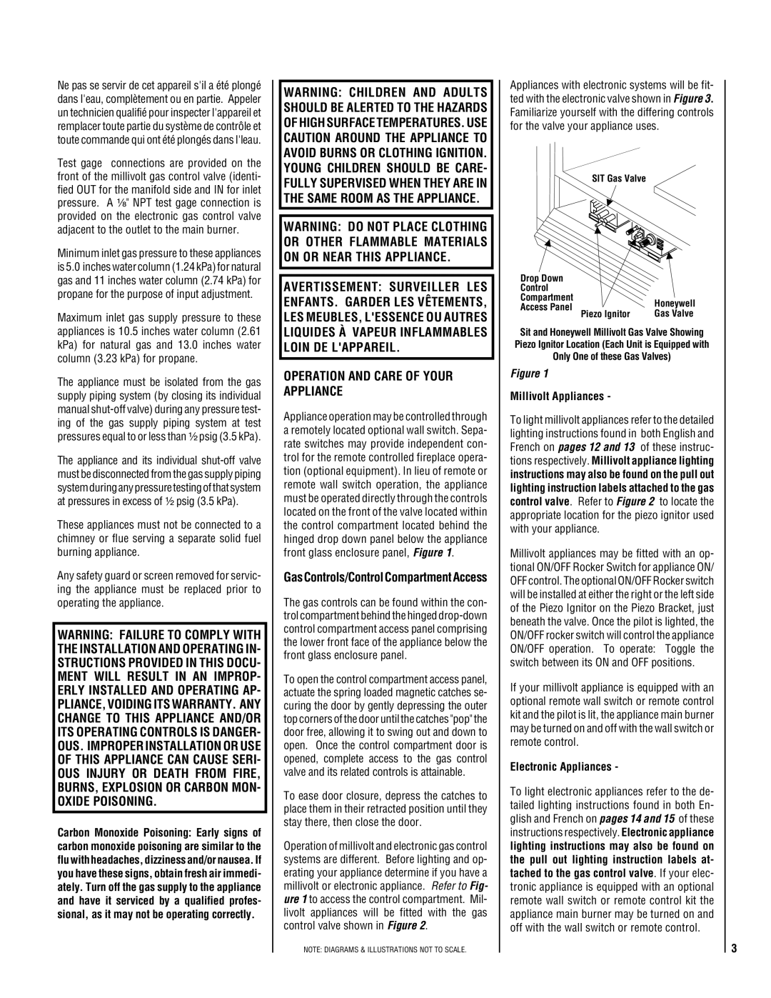
Appliance operation may be controlled through a remotely located optional wall switch. Sepa- rate switches may provide independent con- trol for the remote controlled fireplace opera- tion (optional equipment). In lieu of remote or remote wall switch operation, the appliance must be operated directly through the controls located on the front of the valve located within the control compartment located behind the hinged drop down panel below the appliance front glass enclosure panel, Figure 1.
GasControls/ControlCompartmentAccess
The gas controls can be found within the con- trol compartment behind the hinged
To open the control compartment access panel, actuate the spring loaded magnetic catches se- curing the door by gently depressing the outer top corners of the door until the catches "pop" the door free, allowing it to swing out and down to open. Once the control compartment door is opened, complete access to the gas control valve and its related controls is attainable.
To ease door closure, depress the catches to place them in their retracted position until they stay there, then close the door.
Operation of millivolt and electronic gas control systems are different. Before lighting and op- erating your appliance determine if you have a millivolt or electronic appliance. Refer to Fig- ure 1 to access the control compartment. Mil- livolt appliances will be fitted with the gas control valve shown in Figure 2.
NOTE: DIAGRAMS & ILLUSTRATIONS NOT TO SCALE.
Appliances with electronic systems will be fit- ted with the electronic valve shown in Figure 3. Familiarize yourself with the differing controls for the valve your appliance uses.
SIT Gas Valve
Drop Down |
| |
Control |
| |
Compartment | Honeywell | |
Access Panel Piezo Ignitor | ||
Gas Valve |
Sit and Honeywell Millivolt Gas Valve Showing Piezo Ignitor Location (Each Unit is Equipped with Only One of these Gas Valves)
Figure 1
Millivolt Appliances -
To light millivolt appliances refer to the detailed lighting instructions found in both English and French on pages 12 and 13 of these instruc- tions respectively. Millivolt appliance lighting instructions may also be found on the pull out lighting instruction labels attached to the gas control valve. Refer to Figure 2 to locate the appropriate location for the piezo ignitor used with your appliance.
Millivolt appliances may be fitted with an op- tional ON/OFF Rocker Switch for appliance ON/ OFF control. The optional ON/OFF Rocker switch will be installed at either the right or the left side of the Piezo Ignitor on the Piezo Bracket, just beneath the valve. Once the pilot is lighted, the ON/OFF rocker switch will control the appliance ON/OFF operation. To operate: Toggle the switch between its ON and OFF positions.
If your millivolt appliance is equipped with an optional remote wall switch or remote control kit and the pilot is lit, the appliance main burner may be turned on and off with the wall switch or remote control.
Electronic Appliances -
To light electronic appliances refer to the de- tailed lighting instructions found in both En- glish and French on pages 14 and 15 of these instructions respectively. Electronic appliance lighting instructions may also be found on the pull out lighting instruction labels at- tached to the gas control valve. If your elec- tronic appliance is equipped with an optional remote wall switch or remote control kit the appliance main burner may be turned on and off with the wall switch or remote control.
3