Allow the burner to operate for at least 15 minutes. Observe the flame continuously. If it appears weak or sooty as previously described, adjust the air shutter by pushing or pulling on the adjustment rod until the flame appearance is as desired.
The adjustment rod and associated adjustable air shutter is patented technology. Flame ad- justments can be made quickly and accurately to taste without the need of disassembling the appliance and waiting for 30 minutes after each adjustment.
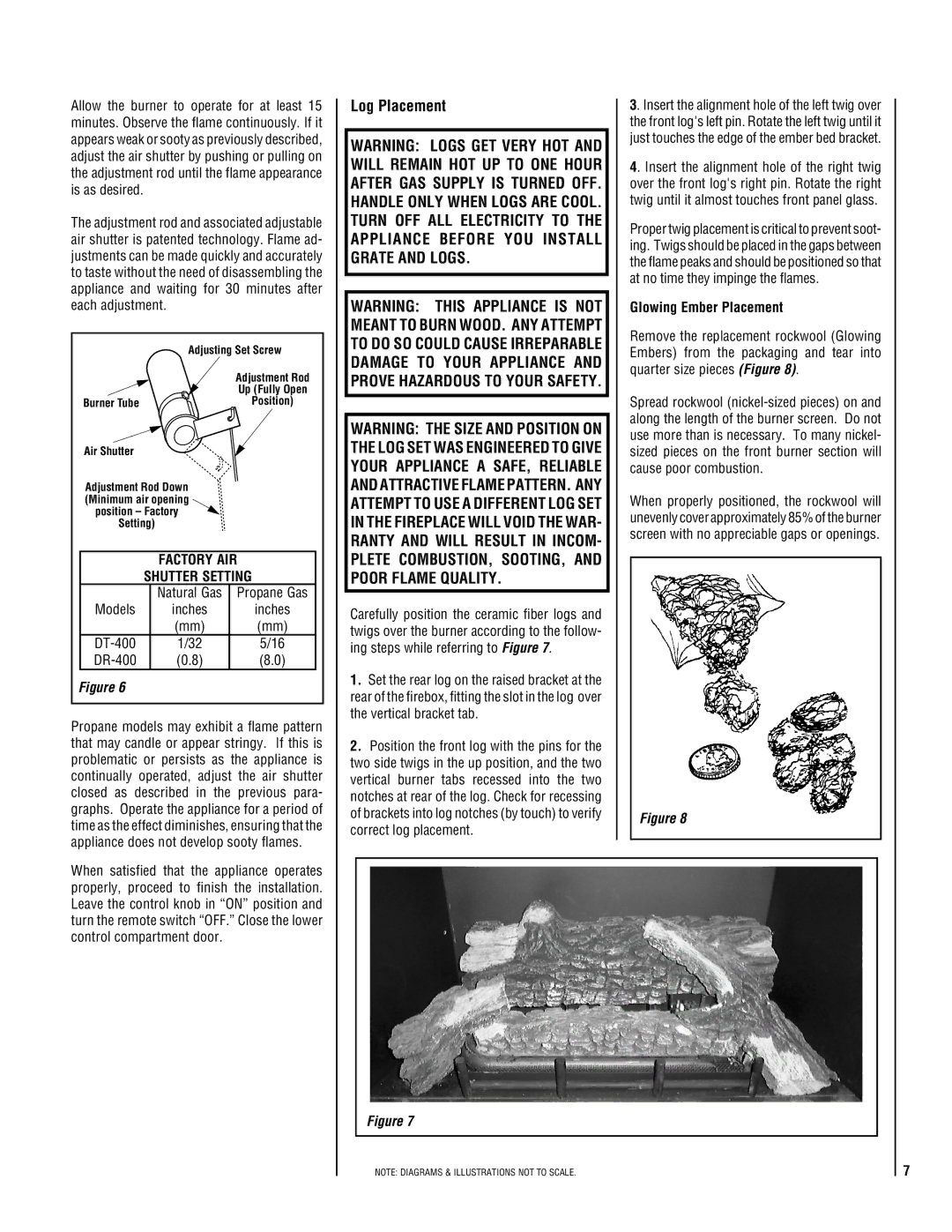
| Adjusting Set Screw | |
|
| Adjustment Rod |
|
| Up (Fully Open |
Burner Tube |
| Position) |
|
| |
Air Shutter |
|
|
Adjustment Rod Down |
| |
(Minimum air opening |
| |
position – Factory |
| |
Setting) |
| |
| FACTORY AIR | |
| SHUTTER SETTING | |
| Natural Gas | Propane Gas |
Models | inches | inches |
| (mm) | (mm) |
| 1/32 | 5/16 |
| (0.8) | (8.0) |
Figure 6
Propane models may exhibit a flame pattern that may candle or appear stringy. If this is problematic or persists as the appliance is continually operated, adjust the air shutter closed as described in the previous para- graphs. Operate the appliance for a period of time as the effect diminishes, ensuring that the appliance does not develop sooty flames.
When satisfied that the appliance operates properly, proceed to finish the installation. Leave the control knob in “ON” position and turn the remote switch “OFF.” Close the lower control compartment door.
Log Placement
WARNING: LOGS GET VERY HOT AND WILL REMAIN HOT UP TO ONE HOUR AFTER GAS SUPPLY IS TURNED OFF. HANDLE ONLY WHEN LOGS ARE COOL. TURN OFF ALL ELECTRICITY TO THE APPLIANCE BEFORE YOU INSTALL GRATE AND LOGS.
WARNING: THIS APPLIANCE IS NOT MEANT TO BURN WOOD. ANY ATTEMPT TO DO SO COULD CAUSE IRREPARABLE DAMAGE TO YOUR APPLIANCE AND PROVE HAZARDOUS TO YOUR SAFETY.
WARNING: THE SIZE AND POSITION ON THE LOG SET WAS ENGINEERED TO GIVE YOUR APPLIANCE A SAFE, RELIABLE AND ATTRACTIVE FLAME PATTERN. ANY ATTEMPT TO USE A DIFFERENT LOG SET IN THE FIREPLACE WILL VOID THE WAR- RANTY AND WILL RESULT IN INCOM- PLETE COMBUSTION, SOOTING, AND POOR FLAME QUALITY.
Carefully position the ceramic fiber logs and twigs over the burner according to the follow- ing steps while referring to Figure 7.
1.Set the rear log on the raised bracket at the rear of the firebox, fitting the slot in the log over the vertical bracket tab.
2.Position the front log with the pins for the two side twigs in the up position, and the two vertical burner tabs recessed into the two notches at rear of the log. Check for recessing of brackets into log notches (by touch) to verify correct log placement.
3. Insert the alignment hole of the left twig over the front log's left pin. Rotate the left twig until it just touches the edge of the ember bed bracket.
4. Insert the alignment hole of the right twig over the front log's right pin. Rotate the right twig until it almost touches front panel glass.
Proper twig placement is critical to prevent soot- ing. Twigs should be placed in the gaps between the flame peaks and should be positioned so that at no time they impinge the flames.
Glowing Ember Placement
Remove the replacement rockwool (Glowing Embers) from the packaging and tear into quarter size pieces (Figure 8).
Spread rockwool
When properly positioned, the rockwool will unevenly cover approximately 85% of the burner screen with no appreciable gaps or openings.
Figure 8
Figure 7
NOTE: DIAGRAMS & ILLUSTRATIONS NOT TO SCALE.
7