If your electronic appliance is not equipped with a wall switch or remote control, the main burner must be turned off and on with the gas control switch. Toggle the switch from ON to OFF to operate the main burner .
Manifold Pressure Port | ON/OFF Switch | |||
CONTROL | OFF ON | IN | Inlet | |
Pressure | ||||
IGNITER |
|
| ||
|
| Port | ||
|
|
| ||
|
| PSI |
| |
|
|
| Electronic | |
|
|
| Gas Control | |
|
|
| Valve | |
Honeywell Electronic Gas Valve | ||||
Figure 2 |
|
|
| |
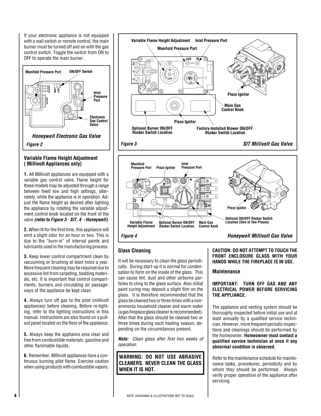
Variable Flame Height Adjustment ( Millivolt Appliances only)
1. All Millivolt appliances are equipped with a |
variable gas control valve. Flame height for |
these models may be adjusted through a range |
between fixed low and high settings, alter- |
nately, while the appliance is in operation. Ad- |
just the flame height as desired after lighting |
the appliance by rotating the variable adjust- |
ment control knob located on the front of the |
valve (refer to Figure 3 - SIT, 4 - Honeywell). |
2. When lit for the first time, this appliance will |
emit a slight odor for an hour or two. This is |
due to the |
lubricants used in the manufacturing process. |
Variable Flame Height Adjustment | Inlet Pressure Port | ||
| Manifold Pressure Port | ||
|
| OUT | IN |
TPTH |
|
|
|
| I |
|
|
TP | H |
|
|
| OFF |
| |
|
| P | |
|
|
| |
|
|
| I |
TH | L OW |
| L |
it | O | ||
|
| NO | T |
|
|
| |
| P |
|
|
| LI |
|
|
| TO |
|
|
|
|
| Piezo Ignitor |
|
|
| Main Gas |
|
|
| Control Knob |
|
| Piezo Ignitor | |
Optional Burner ON/OFF |
| ||
Rocker Switch Location |
| Rocker Switch Location | |
Figure 3 |
|
| SIT Millivolt Gas Valve |
Manifold |
|
| Inlet |
|
| |
Pressure Port | Piezo Ignitor |
| Pressure Port |
| ||
|
| T OF | F |
|
| |
|
| O |
|
|
| |
| I | L |
|
|
|
|
H |
|
|
|
|
| |
I | P |
|
|
|
|
|
O |
|
|
|
|
|
|
L | N |
|
|
|
|
|
|
|
|
|
|
| |
| O |
|
|
|
|
|
|
|
|
|
|
| Piezo Ignitor |
|
|
|
|
|
| Optional ON/OFF Rocker Switch |
Variable Flame | Optional Burner ON/OFF | Main Gas | Location (One of Two Places) | |||
Height Adjustment | Rocker Switch Location | Control Knob |
| |||
Figure 4 |
|
|
|
|
| Honeywell Millivolt Gas Valve |
3. Keep lower control compartment clean by |
vacuuming or brushing at least twice a year. |
More frequent cleaning may be required due to |
excessive lint from carpeting, bedding materi- |
als, etc. It is important that control compart- |
ments, burners and circulating air passage- |
ways of the appliance be kept clean. |
4. Always turn off gas to the pilot (millivolt |
appliances) before cleaning. Before |
ing, refer to the lighting instructions in this |
manual. Instructions are also found on a pull- |
out panel located on the floor of the appliance. |
5. Always keep the appliance area clear and |
free from combustible materials, gasoline and |
other flammable liquids. |
6. Remember, Millivolt appliances have a con- |
tinuous burning pilot flame. Exercise caution |
when using products with combustible vapors. |
Glass Cleaning
It will be necessary to clean the glass periodi- cally. During
Note: Clean glass after first two weeks of operation.
WARNING: DO NOT USE ABRASIVE CLEANERS. NEVER CLEAN THE GLASS WHEN IT IS HOT.
CAUTION: DO NOT ATTEMPT TO TOUCH THE FRONT ENCLOSURE GLASS WITH YOUR HANDS WHILE THE FIREPLACE IS IN USE.
Maintenance
IMPORTANT: TURN OFF GAS AND ANY ELECTRICAL POWER BEFORE SERVICING THE APPLIANCE.
The appliance and venting system should be thoroughly inspected before initial use and at least annually by a qualified service techni- cian. However, more frequent periodic inspec- tions and cleanings should be performed by the homeowner. Homeowner must contact a qualified service technician at once if any abnormal condition is observed.
Refer to the maintenance schedule for mainte- nance tasks, procedures, periodicity and by whom they should be performed. Always verify proper operation of the appliance after servicing.
4
NOTE: DIAGRAMS & ILLUSTRATIONS NOT TO SCALE.