6
Front Glass Enclosure Panel, Removal and Installation.
WARNING: NEVER OPERATE THE AP- PLIANCE WITHOUT THE FRONT GLASS ENCLOSURE PANEL IN PLACE AND SE- CURE. DO NOT OPERATE APPLIANCE WITH FRONT GLASS CRACKED, BRO- KEN OR MISSING. REPLACEMENT MUST BE DONE BY A LICENSED OR QUALIFIED SERVICE TECHNICIAN.
These are
WARNING: HANDLE THIS GLASS WITH EXTREME CARE! TEMPERED GLASS IS SUSCEPTIBLE TO DAMAGE – DO NOT SCRATCH OR HANDLE ROUGHLY WHILE REINSTALLING THE GLASS DOOR FRAME.
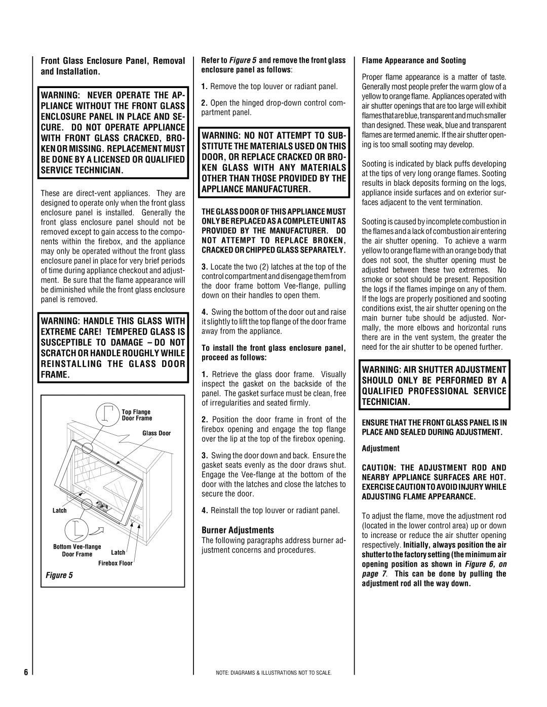
| Top Flange |
| Door Frame |
| Glass Door |
Latch |
|
Bottom | |
Door Frame | Latch |
| Firebox Floor |
Figure 5 |
|
Refer to Figure 5 and remove the front glass enclosure panel as follows:
1.Remove the top louver or radiant panel.
2.Open the hinged
WARNING: NO NOT ATTEMPT TO SUB- STITUTE THE MATERIALS USED ON THIS DOOR, OR REPLACE CRACKED OR BRO- KEN GLASS WITH ANY MATERIALS OTHER THAN THOSE PROVIDED BY THE APPLIANCE MANUFACTURER.
THE GLASS DOOR OF THIS APPLIANCE MUST ONLY BE REPLACED AS A COMPLETE UNIT AS PROVIDED BY THE MANUFACTURER. DO NOT ATTEMPT TO REPLACE BROKEN, CRACKED OR CHIPPED GLASS SEPARATELY.
3.Locate the two (2) latches at the top of the control compartment and disengage them from the door frame bottom
4.Swing the bottom of the door out and raise it slightly to lift the top flange of the door frame away from the appliance.
To install the front glass enclosure panel, proceed as follows:
1.Retrieve the glass door frame. Visually inspect the gasket on the backside of the panel. The gasket surface must be clean, free of irregularities and seated firmly.
2.Position the door frame in front of the firebox opening and engage the top flange over the lip at the top of the firebox opening.
3.Swing the door down and back. Ensure the gasket seats evenly as the door draws shut. Engage the
4.Reinstall the top louver or radiant panel.
Burner Adjustments
The following paragraphs address burner ad- justment concerns and procedures.
NOTE: DIAGRAMS & ILLUSTRATIONS NOT TO SCALE.
Flame Appearance and Sooting
Proper flame appearance is a matter of taste. Generally most people prefer the warm glow of a yellow to orange flame. Appliances operated with air shutter openings that are too large will exhibit flamesthatareblue,transparentandmuchsmaller than designed. These weak, blue and transparent flames are termed anemic. If the air shutter open- ing is too small sooting may develop.
Sooting is indicated by black puffs developing at the tips of very long orange flames. Sooting results in black deposits forming on the logs, appliance inside surfaces and on exterior sur- faces adjacent to the vent termination.
Sooting is caused by incomplete combustion in the flames and a lack of combustion air entering the air shutter opening. To achieve a warm yellow to orange flame with an orange body that does not soot, the shutter opening must be adjusted between these two extremes. No smoke or soot should be present. Reposition the logs if the flames impinge on any of them. If the logs are properly positioned and sooting conditions exist, the air shutter opening on the main burner tube should be adjusted. Nor- mally, the more elbows and horizontal runs there are in the vent system, the greater the need for the air shutter to be opened further.
WARNING: AIR SHUTTER ADJUSTMENT SHOULD ONLY BE PERFORMED BY A QUALIFIED PROFESSIONAL SERVICE TECHNICIAN.
ENSURE THAT THE FRONT GLASS PANEL IS IN PLACE AND SEALED DURING ADJUSTMENT.
Adjustment
CAUTION: THE ADJUSTMENT ROD AND NEARBY APPLIANCE SURFACES ARE HOT. EXERCISE CAUTION TO AVOID INJURY WHILE ADJUSTING FLAME APPEARANCE.
To adjust the flame, move the adjustment rod (located in the lower control area) up or down to increase or reduce the air shutter opening respectively. Initially, always position the air shutter to the factory setting (the minimum air opening position as shown in Figure 6, on page 7. This can be done by pulling the adjustment rod all the way down.