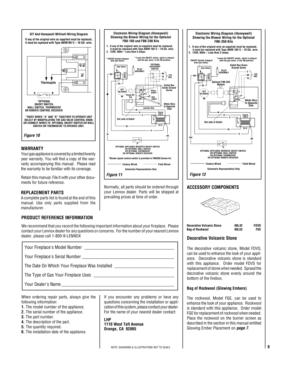
SIT And Honeywell Millivolt Wiring Diagram
If any of the original wire as supplied must be replaced, it must be replaced with Type AWM105° C – 18 GA. wire.
Electronic Wiring Diagram (Honeywell) Showing the Blower Wiring for the Optional
1.If any of the original wire as supplied must be replaced,
1.it must be replaced with Type AWM 105° C – 18 GA. wire.
2.120V, 60Hz – Less than 3 amps.
**ON/OFF Switch (Integral | **Leave the ON/OFF switch, which is integral | |
with the gas valve, in the ON position. | ||
with Gas Valve) | ||
|
Electronic Wiring Diagram (Honeywell) Showing the Blower Wiring for the Optional
1.If any of the original wire as supplied must be replaced,
1.it must be replaced with Type AWM 105° C – 18 GA. wire.
2.120V, 60Hz – Less than 3 amps.
*Leave the ON/OFF switch, which is integral
*ON/OFF Switch (Integral with the gas valve, in the ON position. with Gas Valve)
TP
Thermopile
A ![]() B
B
*OPTIONAL ON/OFF SWITCH,
WALL SWITCH, THERMOSTAT OR REMOTE CONTROL RECEIVER
TH TH TP
|
|
| *OPTIONAL |
|
| Gas Valve |
| ACCESSORY |
|
|
| PILOT | SWITCH |
|
| IGNITER | ASSEMBLY |
| |
BK |
| BK | ||
| W | 120 | ||
|
| |||
|
| VAC. | ||
| R |
| G |
|
|
|
|
| |
| BL |
|
| Outlet Box |
|
|
|
| |
| OPT |
| Green Ground | |
| G | Black | Screw | |
| BLOWER | pigtail |
| |
|
| Break Off | Red |
|
|
| Tab |
| |
|
|
| pigtail |
|
|
|
| White Wire | |
|
|
| to Opposite | |
|
| W | Junction Box | Side |
|
|
| ||
|
| Transf. |
| |
|
| B |
| |
|
| G | 120 V. |
|
|
|
|
|
|
|
| Outlet Box Green |
|
| Gas Valve |
| PILOT | Ground Screw |
| |||
|
|
| ||||||
|
|
|
|
|
| G |
| |
|
|
|
|
|
| ASSEMBLY | 120 | |
|
|
| IGNITER |
|
|
| ||
|
|
|
|
|
| W |
| |
BK |
|
|
|
|
|
| BK | VAC. |
|
|
|
|
|
|
|
| |
|
|
|
|
|
|
|
|
|
|
|
|
|
|
|
|
|
|
ROptional
ModuleBL
OPT |
|
BLOWER | G |
White Wire
To Opposite
Side
W
*TWIST WIRES “A” AND “B” TOGETHER TO OPERATE UNIT SOLELY BY MANIPULATING THE GAS VALVE CONTROL KNOB; OR CONNECT WIRES TO OPTIONAL ON/OFF SWITCH OR WALL SWITCH OR THERMOSTAT TO OPERATE UNIT.
Figure 10
WARRANTY
Your gas appliance is covered by a limited twenty year warranty. You will find a copy of the war- ranty accompanying this manual. Please read the warranty to be familiar with its coverage.
Retain this manual. File it with your other docu- ments for future reference.
REPLACEMENT PARTS
A complete parts list is found at the end of this manual. Use only parts supplied from the manufacturer.
| Hot side of Outlet |
|
| BL | 24 V |
|
| |
|
| R |
W |
| BK |
|
|
OPTIONAL
OR OPTIONAL WALL SWITCH
OR OPTIONAL THERMOSTAT
OR OPTIONAL REMOTE RECEIVER
*Blower speed control switch is provided in FBK200 blower kit.
Factory Wired | Field Wired |
Schematic Representation Only
Figure 11
Normally, all parts should be ordered through your Lennox dealer. Parts will be shipped at prevailing prices at time of order.
G | 120 V. |
Hot side of Outlet |
|
BL | 24 V |
| |
| R |
WH | BK |
| |
OPTIONAL | |
OR OPTIONAL WALL SWITCH |
|
OR OPTIONAL THERMOSTAT |
|
OR OPTIONAL REMOTE RECEIVER |
|
Factory Wired | Field Wired |
Schematic Representation Only
Figure 12
ACCESSORY COMPONENTS
PRODUCT REFERENCE INFORMATION
We recommend that you record the following important information about your fireplace. Please contact your Lennox dealer for any questions or concerns. For the number of your nearest Lennox dealer, please call
Your Fireplace's Model Number _______________________________________
Your Fireplace's Serial Number ________________________________________
The Date On Which Your Fireplace Was Installed __________________________
The Type of Gas Your Fireplace Uses ___________________________________
Your Dealer's Name _________________________________________________
Decorative Volcanic Stone | 80L42 | FDVS |
Bag of Rockwool | 88L53 | FGE |
Decorative Volcanic Stone
The decorative volcanic stone, Model FDVS, can be used to enhance the look of your appli- ance. Decorative volcanic stone is standard with this appliance. Order model FDVS for replacement of stone when needed. Spread the decorative volcanic stone evenly around the bottom of the firebox.
Bag of Rockwool (Glowing Embers)
When ordering repair parts, always give the following information:
1.The model number of the appliance.
2.The serial number of the appliance.
3.The part number.
4.The description of the part.
5.The quantity required.
6.The installation date of the appliance.
If you encounter any problems or have any questions concerning the installation or appli- cation of this system, please contact your dealer. For the name of your nearest dealer contact:
LHP
1110 West Taft Avenue
Orange, CA 92865
The rockwool, Model FGE, can be used to enhance the look of your appliance. Rockwool is standard with this appliance. Order model FGE for replacement of rockwool when needed. Place the rockwool on the burner screen as described in the section in this manual entitled Glowing Ember Placement on page 7.
NOTE: DIAGRAMS & ILLUSTRATIONS NOT TO SCALE.
9