6
Example: The bottom of the mantel may project from the wall a maximum of
12"
10" |
| |
8" | 26" | |
6" | ||
| ||
8" | ||
| ||
Min. |
|
Hood (Canopy)
Heat Resistant
Material
Figure 5
Step 5. Floor clearance: If combustible floor- ing materials, such as carpeting or asphalt tile, are to be located within 14" of the fireplace or firebox opening, the room heater base must be at least 5" above the combustible flooring ma- terial (Figure 6 ).
Combustible
Material
Combustible
Material
5" Min.
Figure 6
The room heater base may be lower than 5" above the combustible flooring materials if the combustible flooring materials are more than 14" from the fireplace or firebox opening (Figure 7 ).
Combustible
Material
Can be less than 5"
14" Min.
(Both Sides Of Opening)
Figure 7
INSTALLATION
WARNING: DO NOT ALLOW FANS TO BLOW DIRECTLY INTO THE FIREPLACE. AVOID ANY DRAFTS THAT ALTER BURNER FLAME PATTERNS.
WARNING: DO NOT USE A BLOWER IN- SERT, HEAT EXCHANGER INSERT OR OTHER ACCESSORY NOT APPROVED FOR USE WITH THIS HEATER.
This appliance must not be operated without a fireplace screen installed. Fireplace screens must not impair the free flow of combustion air to the appliance.
Do not burn solid fuels in any fireplace equipped with this listed unvented gas room heater.
WARNING: INSTALLED DECORATIVE GLASS DOOR ENCLOSURES MUST BE FULLY OPENED WHEN OPERATING THIS LISTED UNVENTED GAS ROOM HEATER.
Any outside air ducts and/or ash dumps that are part of the original solid fuel burning fireplace system must be fully closed and sealed at the time of installation of this listed unvented gas room heater.
WARNING: SPECIAL CARE IS REQUIRED IF YOU ARE INSTALLING THE UNIT INTO A SUNKEN FIREPLACE. YOU MUST RAISE THE FIREPLACE FLOOR TO ALLOW AC- CESS TO GAS LOG CONTROLS. THIS WILL INSURE ADEQUATE AIR FLOW AND GUARD AGAINST SOOTING. RAISE THE FIREPLACE FLOOR USING NONCOMBUS- TIBLE MATERIALS.
A qualified gas appliance installer must install this heater.
Check gas type: The gas supply must be the same as stated on the heater’s rating plate. If the gas supply is different, DO NOT INSTALL the heater. Contact your dealer for the correct model.
Step 1. Placement of Heater – Center the heater in the fireplace or firebox. Make certain the grate front feet sit inside the front edge of the fireplace or firebox.
NOTE: DIAGRAMS & ILLUSTRATION NOT TO SCALE.
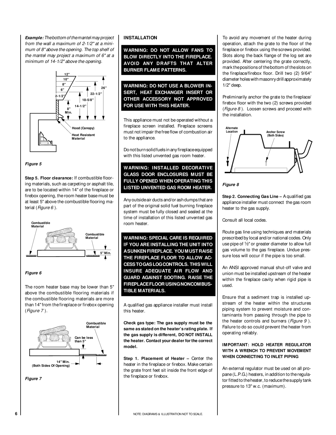
To avoid any movement of the heater during operation, attach the grate to the floor of the fireplace or firebox using the screws provided. Slots along the back flange of the log set are provided. After centering the grate correctly, mark the positions of the bottom of the slots on the fireplace/firebox floor. Drill two (2) 9/64" diameter holes with masonry drill approximately 1/2" deep.
Preliminarily anchor the grate to the fireplace/ firebox floor with the two (2) screws provided (Figure 8 ). Loosen screws and proceed with the installation.
Alternate
LocationAnchor Screw
(Both Sides)
Figure 8
Step 2. Connecting Gas Line – A qualified gas appliance installer must connect the gas room heater to the gas supply.
Consult all local codes.
Route gas line using techniques and materials prescribed by local and/or national codes. Only use pipe of ¹⁄₂" or greater diameter to allow full gas volume to the gas fireplace. Undue pres- sure loss will occur if the pipe is too small.
An ANSI approved manual
Ensure that a sediment trap is installed up- stream of the heater within the structures piping system to prevent moisture and con- taminants from passing through the pipe to the heater controls and burners (Figure 9 ). Failure to do so could prevent the heater from operating reliably.
IMPORTANT: HOLD HEATER REGULATOR WITH A WRENCH TO PREVENT MOVEMENT WHEN CONNECTING TO INLET PIPING
An external regulator must be used on all pro- pane (L.P.G.) heaters, in addition to the regula- tor fitted to the heater, to reduce the supply tank pressure to 13" w.c. (maximum).