8
Flame Appearance
REFER TO THE OPERATING INSTRUCTIONS LOCATED AT THE BACK OF THIS MANUAL BEFORE LIGHTING THE HEATER TO OBSERVE THE FLAMES.
Flames from the pilot, front and rear burner should be visually checked as soon as the heater is installed. In addition a periodic visual check of the flames should be made. The pilot flame should always be present when the heater is in operation (Figure 12 ).
WARNING: NO ADJUSTMENTS ARE TO BE MADE TO THE ODS PILOT SYSTEM. TAMPERING WITH THIS SYSTEM CAN BE EXTREMELY HAZARDOUS.
Figure 12
An incorrect pilot flame pattern is shown in Figure 13. This pilot flame will cause the thermocouple to cool. When the thermocouple cools, the log set will shut off. If pilot flame pattern is incorrect, or if log set shuts off, contact your service representative.
Figure 13
In normal operation, at full rate, after 15 min- utes the following flame appearance should be observed:
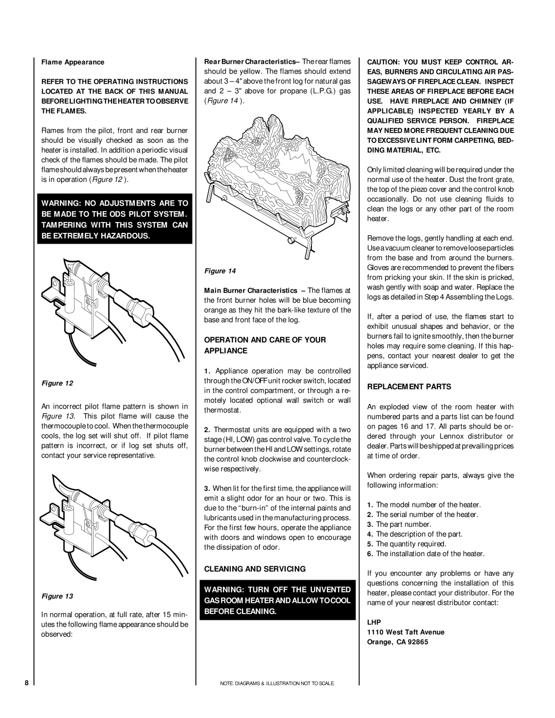
Rear Burner Characteristics– The rear flames should be yellow. The flames should extend about 3 – 4" above the front log for natural gas and 2 – 3" above for propane (L.P.G.) gas (Figure 14 ).
Figure 14
Main Burner Characteristics – The flames at the front burner holes will be blue becoming orange as they hit the
OPERATION AND CARE OF YOUR APPLIANCE
1.Appliance operation may be controlled through the ON/OFF unit rocker switch, located in the control compartment, or through a re- motely located optional wall switch or wall thermostat.
2.Thermostat units are equipped with a two stage (HI, LOW) gas control valve. To cycle the burner between the HI and LOW settings, rotate the control knob clockwise and counterclock- wise respectively.
3.When lit for the first time, the appliance will emit a slight odor for an hour or two. This is due to the
CLEANING AND SERVICING
WARNING: TURN OFF THE UNVENTED GAS ROOM HEATER AND ALLOW TO COOL BEFORE CLEANING.
NOTE: DIAGRAMS & ILLUSTRATION NOT TO SCALE.
CAUTION: YOU MUST KEEP CONTROL AR- EAS, BURNERS AND CIRCULATING AIR PAS- SAGEWAYS OF FIREPLACE CLEAN. INSPECT THESE AREAS OF FIREPLACE BEFORE EACH USE. HAVE FIREPLACE AND CHIMNEY (IF APPLICABLE) INSPECTED YEARLY BY A QUALIFIED SERVICE PERSON. FIREPLACE MAY NEED MORE FREQUENT CLEANING DUE TO EXCESSIVE LINT FORM CARPETING, BED- DING MATERIAL, ETC.
Only limited cleaning will be required under the normal use of the heater. Dust the front grate, the top of the piezo cover and the control knob occasionally. Do not use cleaning fluids to clean the logs or any other part of the room heater.
Remove the logs, gently handling at each end. Use a vacuum cleaner to remove loose particles from the base and from around the burners. Gloves are recommended to prevent the fibers from pricking your skin. If the skin is pricked, wash gently with soap and water. Replace the logs as detailed in Step 4 Assembling the Logs.
If, after a period of use, the flames start to exhibit unusual shapes and behavior, or the burners fail to ignite smoothly, then the burner holes may require some cleaning. If this hap- pens, contact your nearest dealer to get the appliance serviced.
REPLACEMENT PARTS
An exploded view of the room heater with numbered parts and a parts list can be found on pages 16 and 17. All parts should be or- dered through your Lennox distributor or dealer. Parts will be shipped at prevailing prices at time of order.
When ordering repair parts, always give the following information:
1.The model number of the heater.
2.The serial number of the heater.
3.The part number.
4.The description of the part.
5.The quantity required.
6.The installation date of the heater.
If you encounter any problems or have any questions concerning the installation of this heater, please contact your distributor. For the name of your nearest distributor contact:
LHP
1110 West Taft Avenue
Orange, CA 92865