Manual
Regulator Union
Valve
| Fireplace or |
| Firebox Wall |
Fireplace or | Wall |
Firebox Wall | Key |
3"Sediment
Trap
Down
Figure 9
WARNING: CONNECTING DIRECTLY TO AN UNREGULATED PROPANE TANK MAY CAUSE AN EXPLOSION.
The heater gas inlet connection is 3/8" NPT at the regulator, located on the right side facing the heater. If a left side connection is required, the connection pipe may be piped under the rear of the appliance to end at the left hand side for connection to the inlet.
When tightening up the joint to the regulator hold the regulator securely with a wrench to prevent the regulator from moving.
Checking Gas Connections: Turn on gas sup- ply and test for gas leaks using a gas leak test solution (also referred to as bubble leak solu- tion). NOTE: using a soapy water solution (50% dish soap, 50% water) is an effective leak test solution, but it is not recommended, be- cause the soap residue that is left on the pipes/ fittings can result in corrosion over time.
A. Light the appliance (refer to the lighting instructions label in the control compartment or on pages 12 or 14).
B. Brush all joints and connections with the gas leak test solution to check for leaks. If bubbles are formed, or gas odor is detected, turn the gas control knob (off/pilot/on) to the “OFF” position. Either tighten or refasten the leaking connection, then retest as described above.
C. When the gas lines are tested and leak free, be sure to rinse off the leak testing solution.
D. Observe the individual tongues of flame on the burner. Make sure all ports are open and producing flame evenly across the burner. If any ports are blocked, or partially blocked, clean out the ports.
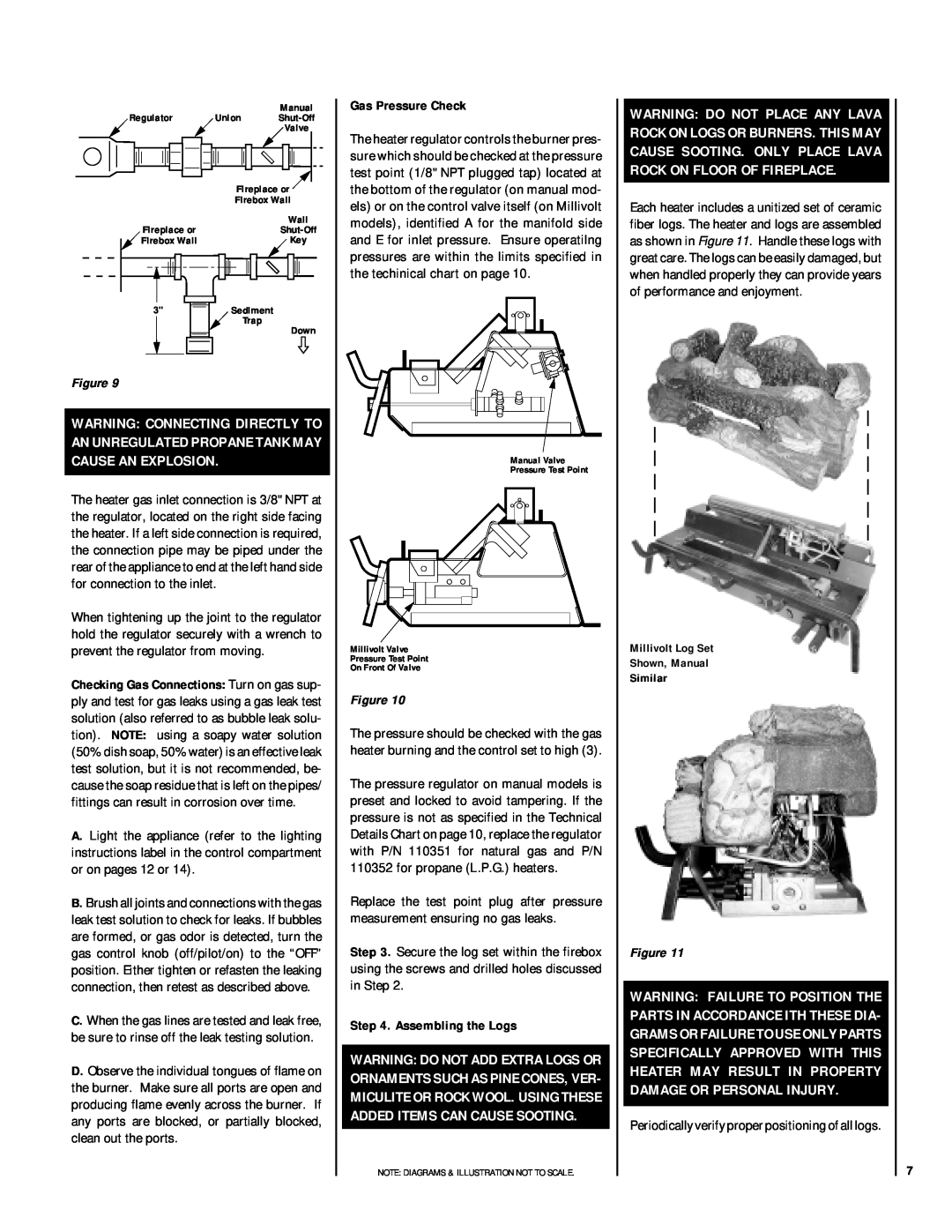
Gas Pressure Check
The heater regulator controls the burner pres- sure which should be checked at the pressure test point (1/8" NPT plugged tap) located at the bottom of the regulator (on manual mod- els) or on the control valve itself (on Millivolt models), identified A for the manifold side and E for inlet pressure. Ensure operatilng pressures are within the limits specified in the techinical chart on page 10.
Manual Valve
Pressure Test Point
Millivolt Valve
Pressure Test Point
On Front Of Valve
Figure 10
The pressure should be checked with the gas heater burning and the control set to high (3).
The pressure regulator on manual models is preset and locked to avoid tampering. If the pressure is not as specified in the Technical Details Chart on page 10, replace the regulator with P/N 110351 for natural gas and P/N 110352 for propane (L.P.G.) heaters.
Replace the test point plug after pressure measurement ensuring no gas leaks.
Step 3. Secure the log set within the firebox using the screws and drilled holes discussed in Step 2.
Step 4. Assembling the Logs
WARNING: DO NOT ADD EXTRA LOGS OR ORNAMENTS SUCH AS PINE CONES, VER- MICULITE OR ROCK WOOL. USING THESE ADDED ITEMS CAN CAUSE SOOTING.
NOTE: DIAGRAMS & ILLUSTRATION NOT TO SCALE.
WARNING: DO NOT PLACE ANY LAVA ROCK ON LOGS OR BURNERS. THIS MAY CAUSE SOOTING. ONLY PLACE LAVA ROCK ON FLOOR OF FIREPLACE.
Each heater includes a unitized set of ceramic fiber logs. The heater and logs are assembled as shown in Figure 11. Handle these logs with great care. The logs can be easily damaged, but when handled properly they can provide years of performance and enjoyment.
Millivolt Log Set
Shown, Manual
Similar
Figure 11
WARNING: FAILURE TO POSITION THE PARTS IN ACCORDANCE ITH THESE DIA- GRAMS OR FAILURE TO USE ONLY PARTS SPECIFICALLY APPROVED WITH THIS HEATER MAY RESULT IN PROPERTY DAMAGE OR PERSONAL INJURY.
Periodically verify proper positioning of all logs.
7