Installation
Tools and supplies needed:
You will need the following items: two pieces of 2x stock to match your existing framing, a saw to cut the hole in the ceiling, a ham- mer or screw gun to attach the blocking to the existing joists, a Phillips head screw driver to attach the grille, weather strip mate- rial and low expansion spray foam sealant.
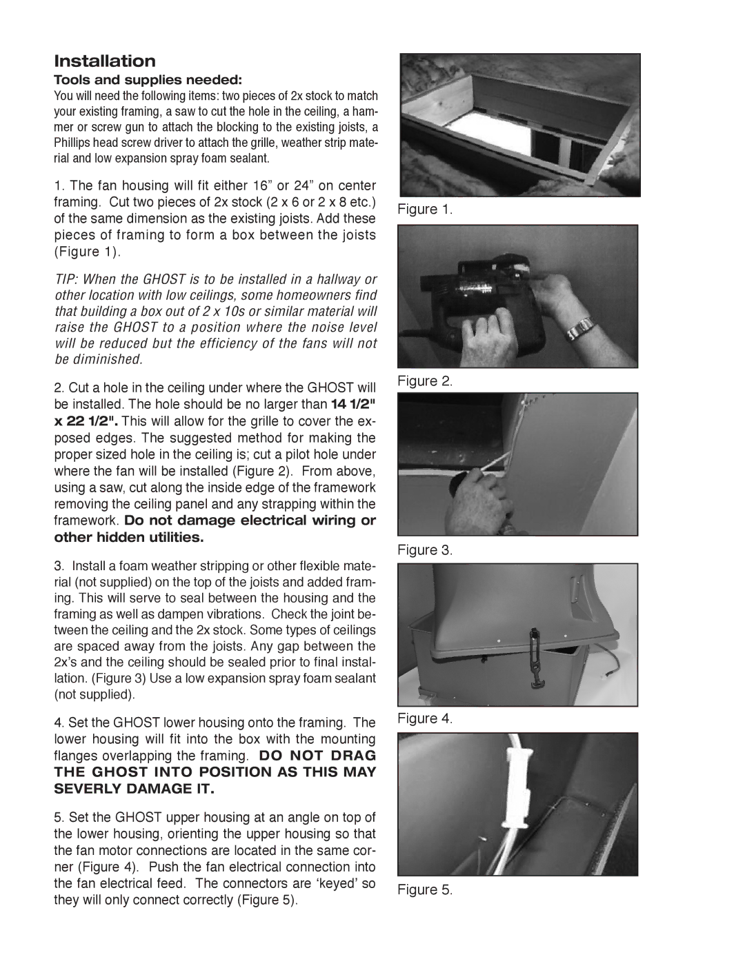
1.The fan housing will fit either 16” or 24” on center framing. Cut two pieces of 2x stock (2 x 6 or 2 x 8 etc.) of the same dimension as the existing joists. Add these pieces of framing to form a box between the joists (Figure 1).
TIP: When the GHOST is to be installed in a hallway or other location with low ceilings, some homeowners find that building a box out of 2 x 10s or similar material will raise the GHOST to a position where the noise level will be reduced but the efficiency of the fans will not be diminished.
2.Cut a hole in the ceiling under where the GHOST will be installed. The hole should be no larger than 14 1/2" x 22 1/2". This will allow for the grille to cover the ex- posed edges. The suggested method for making the proper sized hole in the ceiling is; cut a pilot hole under where the fan will be installed (Figure 2). From above, using a saw, cut along the inside edge of the framework removing the ceiling panel and any strapping within the framework. Do not damage electrical wiring or other hidden utilities.
3.Install a foam weather stripping or other flexible mate- rial (not supplied) on the top of the joists and added fram- ing. This will serve to seal between the housing and the framing as well as dampen vibrations. Check the joint be- tween the ceiling and the 2x stock. Some types of ceilings are spaced away from the joists. Any gap between the 2x’s and the ceiling should be sealed prior to final instal- lation. (Figure 3) Use a low expansion spray foam sealant (not supplied).
4.Set the GHOST lower housing onto the framing. The lower housing will fit into the box with the mounting flanges overlapping the framing. DO NOT DRAG
THE GHOST INTO POSITION AS THIS MAY SEVERLY DAMAGE IT.
5.Set the GHOST upper housing at an angle on top of the lower housing, orienting the upper housing so that the fan motor connections are located in the same cor- ner (Figure 4). Push the fan electrical connection into the fan electrical feed. The connectors are ‘keyed’ so they will only connect correctly (Figure 5).
Figure 1.
Figure 2.
Figure 3.
Figure 4.
Figure 5.