TANDBERG |
|
Telepresence T3 | Table Connection notes |
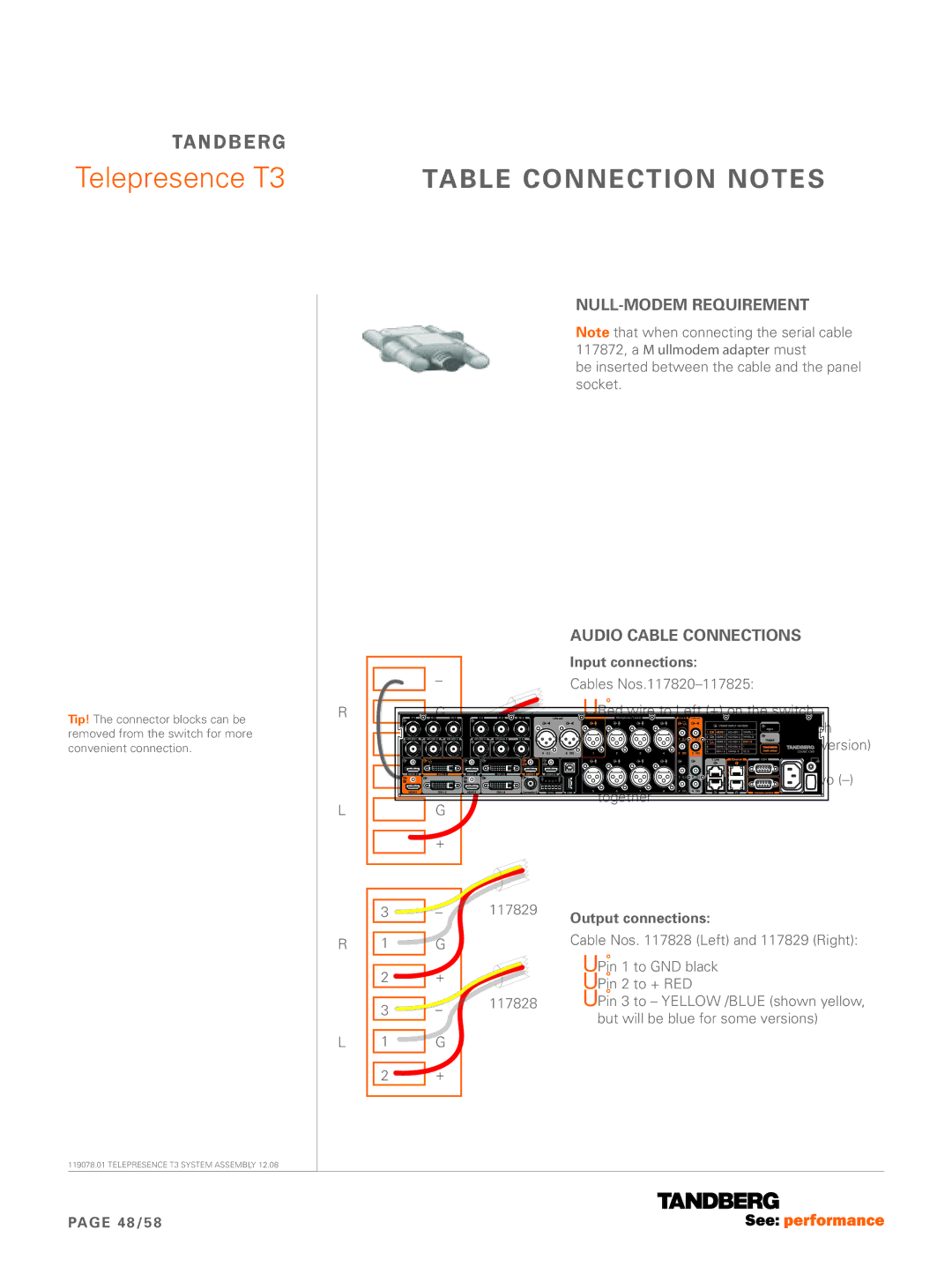
Tip! The connector blocks can be removed from the switch for more convenient connection.
119078.01 TELEPRESENCE T3 SYSTEM ASSEMBLY 12.08
R
L
R
L
3
1
2
3
1
2
–
G
+
–
G
+
–
G
+
–
G
+
117829
117828
Null-modem requirement
Note that when connecting the serial cable 117872, a KRAMER
Audio cable connections
Input connections:
Cables
•Red wire to Left (+) on the switch
•Black (GND) to Left
•White, yellow or blue (depends on version) wire to Right (+) on the switch
•Use a short cable to connect the two
Output connections:
Cable Nos. 117828 (Left) and 117829 (Right):
•Pin 1 to GND black
•Pin 2 to + RED
•Pin 3 to – YELLOW /BLUE (shown yellow, but will be blue for some versions)
PAGE 48/58
