TANDBERG |
|
Telepresence T3 | system assembly guide |
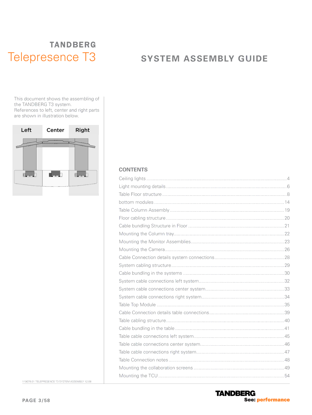
This document shows the assembling of the TANDBERG T3 system.
References to left, center and right parts are shown in illustration below.
119078.01 TELEPRESENCE T3 SYSTEM ASSEMBLY 12.08
Contents |
|
Ceiling lights | 4 |
Light mounting details | 6 |
Table Floor structure | 8 |
bottom modules | 14 |
Table Column Assembly | 19 |
Floor cabling structure | 20 |
Cable bundling Structure in Floor | 21 |
Mounting the Column tray | 22 |
Mounting the Monitor Assemblies | 23 |
Mounting the Camera | 26 |
Cable Connection details system connections | 28 |
System cabling structure | 29 |
Cable bundling in the systems | 30 |
System cable connections left system | 32 |
System cable connections center system | 33 |
System cable connections right system | 34 |
Table Top Module | 35 |
Cable Connection details table connections | 39 |
Table cabling structure | 40 |
Cable bundling in the table | 41 |
Table cable connections left system | 45 |
Table cable connections center system | 46 |
Table cable connections right system | 47 |
Table Connection notes | 48 |
Mounting the collaboration screens | 49 |
Mounting the TCU | 54 |
PAGE 3/58